
By Dr. Pradyumna Gupta, Founder & Chief Scientist, Infinita Lab | Founder & CEO, Infinita Materials
When an AI accelerator die dissipates 700 watts across a surface smaller than a playing card, with a thermal management chain holding that system together, it is under thermal pressure that much of its component material was never qualified to experience. Silicon, package substrate, and cold plate have all been engineered with precision. The interface between them filled with Thermal Interface Material (TIM) is almost always where the performance validation stops.
TIM is nothing new in semiconductor packaging; they have existed in microelectronics for decades. There is a whole universe of them—polymer pads, phase-change materials, and metallic TIMs built on In or Ga alloy bases. What is new is the density that AI computing has ushered in. With values of 300–700 W per die, and package power densities that in some configurations can exceed 100 W/cm², TIMs are being asked to perform under specifications to which they are not qualified. The gap is growing between TIM datasheets and the TIM performance that exists at the operating conditions required by current-generation AI hardware.
Why Datasheet Thermal Conductivity Is Not Enough
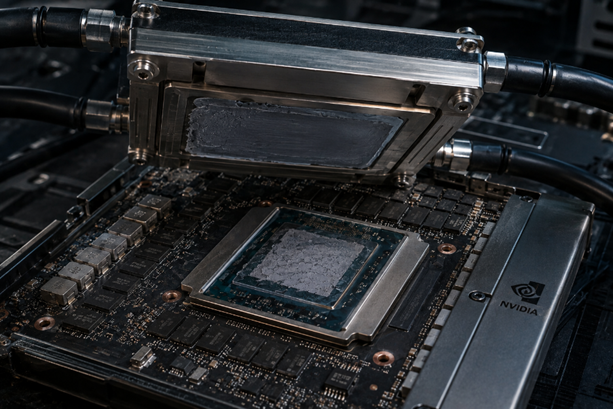
When it comes to evaluating thermal interface materials (TIMs), spec engineers gravitate to bulk thermal conductivity measured in W/m·K. It is a real number, but it characterizes only one aspect of TIM performance—not necessarily the one most relevant to reliability in a product system. Real-world junction-to-case thermal resistance depends on the sum of the bulk thermal resistance of the TIM and the contact thermal resistance at the TIM-to-surface interfaces.
That contact thermal resistance depends strongly on surface condition, bondline thickness, and pressure applied during assembly.
A high-conductivity TIM might produce worse interface resistance than a lower-conductivity material if it is poorly matched to a mildly rough die or heat-spreader surface and cannot spread. For the power densities of AI accelerators, a 0.05 °C·cm²/W difference in effective resistance would amount to several degrees of die temperature under full power—a difference that can matter with respect to die throttling and long-term reliability. Unfortunately, traditional TIM thermal performance evaluations per ASTM E1530 or ASTM D5470 are performed under carefully controlled pressures and surfaces that probably bear little resemblance to what develops in a packaged assembly, where process variation leads to variations in surface flatness, applied pressures, and bondline integrity.
The Long-Term Behavior Problem
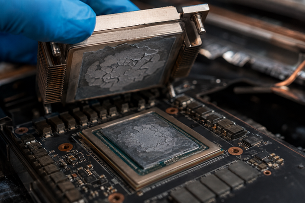
Beyond thermal performance at application debut, the in-application lifetime behavior is where qualification gaps have the greatest impact. Polymer-based TIMs (usually made with either silicones or epoxies as the binder, or “matrix,” with thermally conductive particles embedded therein) are susceptible to what has traditionally been termed “pump-out” or “dry-out” under cyclic thermomechanical loading. As the device package structure expands and contracts through various temperature levels under thermal cycling, the matrix material can be driven away from the interfaces it was meant to bind—ultimately creating an interface bondline with elevated thermal resistance.

The speed at which this happens is highly dependent upon the matrix viscosity, fill concentration and shape, thermal cycling profile, and the energies associated with the substrates involved.
The test vehicles and cycling profiles are typically performed per JEDEC JESD22-A104, which generate useful information on such behavior. However, the temperature ranges and cycle frequency found in such test standards fall far short of those imposed during actual operation of high-thermal-power AI hardware under rapid load transients and elevated maximum temperatures common during use in a typical data-center environment. Metallic TIMs (e.g., low-temperature melting gallium alloys in liquid-metal or phase-change embodiments) offer an order-of-magnitude jump in conductivity over polymer TIMs—roughly 25–40 W/m·K—without polymer pump-out and are utilized in some high-performance processors (workstation and some high-end desktop) to achieve these thermal performance gains. Unfortunately, however, such gallium alloys are more or less toxic toward aluminum and some copper materials, and the resulting galvanic corrosion between the TIM and heat-spreader interface must be assessed across the 5–7 year lifetime of typical enterprise-grade equipment, for which accelerated life-cycle test methods are just beginning to catch up.
For example, indium alloys, employed as solid phase, are the “in-between,” offering conductivity higher than many polymers while being more chemically forgiving than gallium, yet remaining vulnerable to “creep” (physical deformation under static load) and fatigue when stressed, as can occur under the substantial stresses experienced by a high-temperature AI component.
Indeed, the phenomenon is well-characterized as a function of its temperature—near 50–60 percent of its melting point on the Kelvin scale, the operating regime for high-power AI devices—and the effective rate is a direct result of this temperature and the resultant specimen stresses.
What Adequate TIM Qualification Requires
The existing TIM qualification program, to adequately characterize current AI hardware, must also encompass four areas not fully covered by typical datasheets:
First, in-situ thermal resistance characterization at actual operating loads, rather than at the standardized, highly idealized conditions used in a standard test fixture. Specifically, this means testing under conditions that are as close as possible to the actual field environment’s mounting environment, i.e., a comparable surface finish and clamp-pressure distribution, a similar variability of bond-line thickness, and similar constraints.
Second, thermomechanical cyclic testing under conditions that will be experienced in AI hardware. Specifically, this means thermal cycles that have high rates of temperature ramp, are cycled between high peak temperatures and low peak temperatures, and allow for sufficient dwells at the extremes to reach that extreme’s steady-state temperature as used in production systems. Standard test methods with their typical simplified triangular ramps and trapezoidal ramp/soak thermal cycles provide no meaningful data here.
Third, characterization of the chemistry at the TIM interface. Specifically, for metallic TIMs this means looking for the earliest signs of galvanic corrosion and intermetallic growth before measurable degradation occurs at the TIM-to-spreader interface, using methods such as cross-sectional SEM-EDS as well as electrochemical impedance spectroscopy of prototype samples.
Fourth, statistical quantification of assembly variation, as actual manufacturing will not reproduce nominal assembly and reliability will be a distribution determined by this variation. There is no correlation of current single-point qualification data to predicting field reliability volumes.
The Design Implication
The real-world implication of this characterization gap for hardware engineers developing thermal solutions for AI accelerators is that selection cannot be dictated solely by the datasheets. The TIM selection must also be supported by evidence from actual operation. This does not necessarily mean each team has to carry out its own entire characterization program.
It means that evidence needs to be available within the value chain—whether in material-supplier application data, through independent studies, or from in-house tests focused on the component-level assembly or entire solution.
When that evidence does not exist, the thermal solution is qualified on paper but not in the hardware.
The power-density requirements of AI compute are not going to get any easier. Increased power envelopes as silicon dies shrink and designs become ever larger, together with ever-more compact forms requiring ever-more efficient cooling techniques like direct-to-chip liquid and immersion cooling, all apply increasing stress to the TIM at every interface. TIM qualification protocols need to adapt. If not, we are destined to discover what happens at the edge in the deployed product on a large scale.
About Dr. Pradyumna Gupta
Dr. Pradyumna Gupta is the Founder and Chief Scientist of Infinita Lab and Infinita Materials, where he leads pioneering work in materials characterization, reliability engineering, and advanced manufacturing. With more than two decades of experience spanning semiconductors, electric mobility, and aerospace systems, he focuses on bridging material science with practical reliability needs. Dr. Gupta’s work centers on enabling high-performance, safe, and sustainable material architectures for next-generation technologies.