Important Note: EE Herald has now (from October 2012) published embedded systems design practice using latest kits from ST Microelectronics and NXP Semiconductors based on the popular ARM Cortex M0 processor core. The old AME 51 kit for which the sample program explained from next paragraph in this module is not avaialable in the market now. We strongly recommend not to use AME 51 kit, instead read our module3b based on ARM Cortex M0 powered ST MIcro's Disocvery kit and and module3a based on ARM Cortex M0 powered NXP LPCXpresso kit to get into practical learning of embedded systems programming. Sample program for ST kit is available at esmod4bsample and esmod6b and sample program for NXP kit is available at esmod4asample and esmod6a.
OK - Let us start now with "real" hardware (board) and real "software".
One thing you should make sure is that you have the hardware board and the necessary software installed on your PC.(if at all you have purchased the OKI development board) and read about the various documents available with that.
Reading of Module-3 is good enough to install h/w and s/w. However if you need further details, search for AME-51 lite on www.okisemi.com for user manual docs of this kit. Click on this link to dowload the same from our website.
First thing you need to have is an "editor". Basically editor is a program by which we can "see" and "alter" source codes. There are plenty of editors available from normal notepad to highly sophisticated editors, which would be part of IDE (Integrated Development Environment). To start with let us start using an editor called "Notepad ++". This is freeware (no need to pay any money for this). You can download this from following link. In case if you can not find this freeware, the ordinary notepad of any windows operating system can be used.
http://sourceforge.net/project/showfiles.php?group_id=95717&package_id=102072
Once you have installed the development environment provided by OKI - you would have "ame51gnu" directory (folder) in C:\ drive. You can browse through various folders in this "C:\ ame51gnu\" and get to know how the source code is organized for examples etc.
674051 Directory
There are at least 4 sub directories within 674051 Directory. Below figure explains the meaning of each of this item.
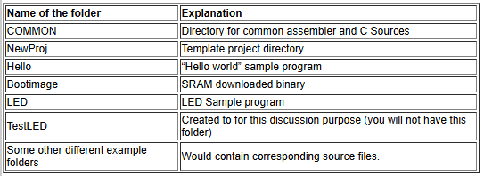
Common Directory holds two more subfolders (i) INC and (ii) SRC.
INC folder holds all the header files for source programs.
SRC holds the common assembler and C programs.
They would be locate at "C:\ame51gnu\Examples\674051\COMMON\INC" and "C:\ame51gnu\Examples\674051\COMMON\SRC" respectively.

The contents of these folders would be shown as below.
Project Directory (example Hello)
This "Hello" directory is taken as an example folder (as most of you would be aware of "Hello world" program in the beginning of your C language learning days). This folder (as well others also) consists of "hello.c" (this would be different for other example programs), "flash.ld" and "Makefile" - this would be same (at least the name of these files) in all other example programs also.
Hello.c : This is the main source program.
Flash.ld : Linker script which defines how the program places into RAM and ROM of the chip
Makefile : It defines the compiler and linker setting. It automates the whole compiling process by just typing "gnumake"
With this background of understanding file structure, how they are organized, and how the typical source code directory would look like (like hello directory), let us start embed ourselves in to our first embedded program.
You should know how an output device is connected (and what is the output device used), intricacies of this output device etc… So let us start our first program with LED. Let us turn ON an LED. Here are the basic steps to be followed.
1) First copy the LED directory as TestLED. Now you would have TestLED folder as well in "C:\ame51gnu\Examples\674051" directory
2) Rename the LED.c in this directory as TestLED.c (you can use dos command "ren" or press "F2" in windows to rename).
3) Open the TestLED.c file with "Notepad++" and delete all the content.
4) Insert the following code in this file (TestLED.c)
int main(void)
{
int i;
volatile unsigned char * ModeRegister;
volatile unsigned char * OutputRegister;
ModeRegister = 0xB7A04008;
OutputRegister = 0xB7A04000;
*ModeRegister = 0x01; // Configure Port E bit 0 as outuput
while (1)
{
*OutputRegister = 0x01; // Set the Port E bit 0 as 1
//Delay
for (i=0; i<1000000; i++)
;
*OutputRegister = 0x00; // Set the Port E bit 0 as 0
//Delay
for (i=0; i<1000000; i++)
;
}
}
5) Open the "Makefile" (in the same directory) and replace the line number 12 as OUT = TestLED . Basically this command tells the compiler to name the outfile as TestLED.hex
6) Now compile the code -
To compile, open the DOS prompt of your system (to open the dos prompt click on the start button/icon of your window OS and look for run in the menu list and click on it. Type "cmd" or "command" in the entry space and click ok). Now the DOS prompt will open to a default location. Now type the DOS command
"cd \ame51gnu\examples\674051\TestLED\" at the DOS prompt.
Type "gnumake" at the DOS prompt to compile. Now the program should compile (any error! read the embedded_kit_manual.pdf. for detailed program compiling and running guidance).
7) After compiling check in the folder \ame51gnu\examples\674051\TestLED\, you could see a new file called TestLED.hex is created. This stores the hexadecibal machine langauge code of this program.
8) Load this TestLED.hex file into the board through serial port connected from PC to board using Tera term pro software already loaded on your PC. To learn how to load the program read embedded_kit_manual.pdf.
9) After loading the program change the switch positions from stand alone mode to SRAM mode and press the reset button.
10)Now you would see the RED LED blinking. It will turn ON and OFF - continuously.

Here is the explanation of the code.
1) Generally any processor or microcontroller would have some ports. These are called General Purpose Input Output (GPIO).
Here you may ask - why these are called GPIO or Ports? If you recall - in earlier days any "goods" that should enter or leave a country would be transported through ships and these ships would be entering or leaving ports of that country. In the same way if you want to send any signal you should put the signal in the port and it would be send. Conversely, if you wish to receive any signal - you should receive (or read) using the ports.
2) The ARM Chipset used in this board has Port 0 to Port 15. Each port has different bit width(some ports has 8 bits, some have 7, some have 6 and some are with only 5, which could be used for any purpose (so called as GPIO).
3) In this example we are using Port E - bit (0). Each port can contain any number of individual bits that can be used (generally port would have 8 bits). This is like saying 8 ships can arrive or depart from this port. Always note that these bits (or anything in embedded world) would be counted from 0! So 8 bits means bit 0 to bit 7 are available.
4) In a way - we are forced to use this Port E - bit( 0), because this is the bit, which is connected to RED LED in our kit. So it is always required for embedded engineers/ programmers to have the complete understanding of the hardware - how it is connected like? what is connected to? where it is connected ?and why. Read the manual embedded_kit_hw_manual.pdf to know how the LEDs are connected.
5) Now we know that, we need to make this Port E - bit (0) high (called some times logical 1 - or simply the voltage becomes +5V) to make the LED to glow and Port E - bit (0) to Low (called some times logical 0 - or simply the voltage becomes 0V) to turn off the LED.
6) You cannot use a port to write and read just like that! You need to tell the processor (in our case ARM chipset) that we are using the particular port and particular bit as output or input. This is like having two-way line - we need to "go" out in left and "come" in back in right. ARM chipset provides a "Mode control" register, which does this job.
7) So in summary - we need to "tell" the processor that we are using Port E - bit (0) as output and make this bit high and low in a continuous loop.
8) Now look at the code once again.
I. "int i" is used as general purpose variable (used for delay).
II. ModeRegister and OutputRegister are used as 8 bit pointers (both have 8 - GPIOs)
III. ModeRegister is at 0xB7A04008 and OutputRegister is at 0xB7A04000 (Note any ports would have address - This address is used to access particular port)
IV. Now configure this Port e - bit 0 as out put by writing 0x01 (as last bit is made 1).
V. Now write 0x01 to OutputRegister to glow the LED and write 0x00 to turn off the LED.
VI. Do this in a loop so that LED turns ON and OFF continuously.
Click on the text below to enter Module-5
ABOUT THIS COURSE:
Totally EEHerald plan to bring 12 modules. You can be assured of completing basic course in Embedded Systems after studying and practicing exercises in all the modules. We will give priority to programming and serial communications (SPI, USB, CAN etc..) part. To receive a copy of total course syllabus, please email to us.
This free tutorials on embedded systems is prepared by embedded professionals with more than10 years of industrial experience, however we want your feedback on this course content; please email your questions, suggestions and comments to editor@eeherald.com. Your questions on present modules will be answered in the revised modules. We may change the course content based on the majority of your requests and feedbacks.
Please let your friends know about this course, we request you to email this link to your friends and colleagues who are interested in embedded system.