Holistic approach in designing reliable electronics board by considering thermal/heat management
Date: 08/10/2023
Designing an electronic system for simple prototyping is different from designing electronic system of production grade. A production grade electronic system design needs lot more effort in terms of making the system reliable, rugged and withstand harsh weather conditions and meet some safety standards and apporvals. Basically the system should last longer when it is operated at its full specified capacity and conditions.
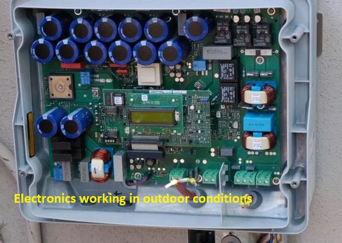
There are so many factors to consider when designing production grade electronic system. One of the important design consideration is managing heat produced by components and also ambient temperature conditions impacting the operating of system.
In electrical and electronic systems every electrical and electronics components conduct electricity that means electrons flow through it. When electron flows through any material they produce heat.That heat can be very minimal or it can rise to very high temperature.
In today’s digital systems there are both signal handling electronics and power handling electronics. Most of the power handling electronics produce heat whereas signal handling electronics normally doesn’t produce that much heat, where you need to really bother about.However today’s high performance processors basically handle digital-computing and signal-processing produce a lot of heat. Signal power amplifiers and RF devices also generate heat.
So let’s look into various aspects of designing electronic system to manage thermal issues.
Minimising thermal issues while designing and selecting components:
Depending on your application, and the geographical areas in which they are going to be used, you should define the operating specifications of the product including operating temperature range,and maximum peak temperature withstanding. However in case of medical, aerospace and defence, designers should also clearly follow the standards for that industry for defining your product specifications. In this article we try to focus more on commercial and industrial grade designs.
List down minimum and maximum (normal operating) and extreme electric power consumption of each device as per your circuit. Select components to match these rating with 10-20% higher than normal operating conditions where components specifications are taken. Select components from reliable source and from vendors who have track record on quality. If you wanto to try out from new vendors, you should test the companent thoroughly before choosing them. More importantly you should study the thermal behaviour specification of devices while are operating at its rated power, voltage and current. This will help you to decide active or passive thermal heat dissipation techniques for those devices which are generating heat excess of 50- 60 Deg C (you can take the choice here whether go-down little or go-up).
While designing printed circuit board for your circuit, following factors need to be considered:
The size of the PCB: since you cannot place heat producing components too close to each other, the size of your PCB should be big enough to accommodate such components with enough space for airflow. Should have a clear picture of physical dimensions (all the three dimensions) of the components to be placed on the PCB. You should ensure copper tracks and pads are big enough to handle the current without generating heat. PCB design software and other tools help here. Keep the ground plane with larger surface area so that it serves to solve both signal integrity and thermal issues.
PCB material: For industrial and automotive grade you generally need more robust PCB material to withstand not only temperature and also other conditions such as vibration, humidity, and salinity.
Placement of components: Although you physically separate digital circuitry, Power circuitry, and RF components and circuitry for the signal interference issues, you also need to look at thermal interference of devices. You should keep heat producing components to the corners, where the stay away from heat sensitive complex SOC chips and other devices.
You should also consider how to utilise metal enclosures to dissipate heat outside the enclosure, however this is not always the case, only in some cases you can leverage enclosures to dissipate heat. Your thermal commonsense should prevail here in taking the right decision in placing the component.
Tracks and pads: Along with your signal integrity issues the track and pads need to handle the power and temperature rise and fall without they undergoing physical and mechanical changes. Use of vias to ground plane, high copper weight, and thermal extreme rise and fall handling not leading cracking is also need to be taken care.
The cost of cooling: ultimately if you're designing a product to generate revenue, the cost of cooling should be optimised as per the requirements. In most cases, designers tend to avoid any external cooling by smartly leveraging passive cooling such as large copper space and wider and thicker copper interconnects on printed circuit board and utilising metal enclosures for cooling. Thermal vias and arrays is also a cheaper option. However if active cooling such as using fans and heatsinks is cheaper than using expensive components, such methods can be employed. It's all depends on what is must to make the product reliable and last longer and offer cost advantage.
Suppose you must use some components which need active thermal dissipation, in most of the cases supplier of the component will provide necessary data on cooling, suggesting all the options available to cool the device. Should carefully read the specifications and try to follow suggested guidelines. If you find your own innovative way to cool the device, you must ensure to thoroughly test your technique before implementing it. You can try to orient the component in a different position than the suggested position to save space or to gain any other advantage.
With your prototype ready and passing the other specifications the system, then try should to evaluate thermal performance of the system by using various methods available in the market. The leading EDA vendors provide thermal analysis software to analyse thermal data. Infrared imaging of the board is most common technique to look at temperature hotspot in the PCB. Try to run the system at its peak performance and later visually inspect as well as do infrared thermal analysis while its operating at its peak. If any errors found with this completion of analysis, you can redesign the board by selecting better component, placing the different position, or using passive and active thermal cooling mechanisms.
Continue this test process several times, until the board finally works without any undesired hotspots. To save cost and time try to utilize expertise in this area to save from redesigning and get success 1st time.
To ensure extra safety and protection against any thermal exceeds, these days engineers are employing thermal management electronics circuits, where temperature sensors such as infrared sensors, thermistors, resistance temperature detectors, and thermocouples are used to detect any temperature anomaly and trigger the protection circuit for actions such as controlling the power, alerting the user, and switching of the system. Engineers can also employ monitoring circuits to monitor cooling such as fan cooling, where is speed of the fan can be controlled and monitored as required.
Now there is also a possibility of using thermal behaviour analysis software tools, to figure out how the heat is generating, spreading and dissipating. These tools support thermal simulation at PCB design level, so that even before physically preparing the board, designers can have a virtual look and analysis of thermal behaviour of both complete system as well as component level thermal behaviour. These softwares perform thermal analysis through models and computational fluid dynamics to analyse the airflow and temperature at various points. The leading EDA companies such as cadence, Siemens EDA, and many more CAD companies offer thermal analysis software for electronic design. One of the popular in this area is Cadence Celsius Thermal Solver for PCB and IC packaging. The software simulates the electro thermal behaviour both in static mode and dynamic mode providing maximum visibility in three-dimensions.
Once the design is completed, if you will still left with devices which produce significant and need to be dissipated using all the available techniques. Those techniques include:
1. Using of heatsinks: heatsinks are generally made of highly thermally conductive materials such as aluminium, copper, mica, and some innovative new materials. You can have a choice of either electrically conductive materials such as aluminium and copper or electrical-insulators but thermally conductive. When you use electrically conductive material you need to shield them with insulating material so that they don't get connected to electrical contacts.
You'll have the problem of RF interference, eddy current. There are very few thermally conductive but electrically insulating material available in the market, and they are generally expensive. Some of such materials include:
Mica sheets, special ceramic sheets, advanced polymer nanocomposites containing orientated boron nitride nanosheets (BNNSs). Laird, a Dupont company makes thermally conductive electrically insulated materials to place between metal heatsinks and the device package. Sur-Cool SFR from a company called SUR-SEAL is fiberglass coated with thermally conductive silicone rubber. Generally heatsinks are designed to have maximum surface area exposed to air, like in the shape of fins. They generally occupy large space compared to the device size itself. Due to this reason, in some of the cases, heatsink is fixed facing outside the PCB, and in some cases it protrudes outside the enclosure itself, so that it gets enough air.
2. The second most used cooling method is, circulating air through cooling fans. Cooling fans are used when the heat generated is significantly high, even after using heatsink. Cooling fans can be placed in parallel to the heat sink, so that it takes a maximum hotair directly from the heatsink. If the whole system/unit is heating up, cooling fans fixed to enclosure itself with a window to exhaust the hotair from the unit.
3. Though rare but in recent times liquid cooling using heat pipes are also employed for cooling electronic systems, these pipes to run through a condenser, whether vaporised liquid converted back to liquid and runs through the pipe placed over hot device to obsorb the heat.
4. polymer based thermal grease and compounds: These paste like materials help in filling the air gap between heat generating surface and the dissipating material.
Let's look at various components of the PCB board, which mostly need thermal management of such devices:
1. High-performance computing processors, FPGA, SoC chips and controllers: a processor with millions and billions of transistors produced significant heat. These days most of the processors are available in the form of system on chips and and lot more functions along with processors inside the chip. For applications such as simple embedded boards, mobile gadgets such as smart phones and many such battery-operated devices, typically these SOC chips are designed not to generate high level of heat and saving the system from not using exclusive heat dissipating devices/systems. But processor/SoC chips for many of the non-mobile processing systems such as desktop computers and even notebook computers, high-performance computing servers and many such computing driven systems generally designed demanding additional cooling system. The cooling system can be a simple heatsink or heatsink with the fans, and even more advanced liquid cooling.
2. Power switching transistors and diodes generate a lot of heat, most of the times they need heatsinks to dissipate heat.
3. Transformers and inductors: In electronics applications, these devices generally produce heat, but is designed with a significantly large copper wire size for the rated current flow, without the need of additional heat dissipating techniques. If they produce significantl high heat, combined with other such heat generating devices, overall box/enclosure cooling can be employed by using cooling fan or large air vents in the enclosure.
References:
PCB Thermal Management Techniques
https://www.allaboutcircuits.com/technical-articles/pcb-thermal-management-techniques/
Thermal Management in Electronic Systems
https://pdfserv.maximintegrated.com/en/an/AN4679.pdf
The Importance of Thermal Management for Power Devices
https://www.eetindia.co.in/the-importance-of-thermal-management-for-power-devices/
Active vs passive cooling: Thermal management of electronic devices
https://www.arrow.com/en/research-and-events/articles/thermal-management-of-electronics-active-vs-passive-cooling
Your Thermal Design Guide for High Power PCBs
https://resources.pcb.cadence.com/blog/2019-your-thermal-design-guide-for-high-power-pcbs
Electronics Cooling Methods for PCB Thermal Management
https://resources.system-analysis.cadence.com/blog/msa2022-electronics-cooling-methods-for-pcb-thermal-management