Part-2
IEEE 802 standards continued .........
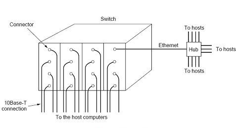
Switched 802.3 LANS
LAN switch is a device with multiple inputs and outputs to interconnect multiple numbers of hosts and computing terminals. LAN switch prevents data packet collision, and maximizes transmission speed as well as bandwidth allocation.
The core job of a switch is to take packets that arrive on an input and forward (or switch) them to the right output so that they will reach their appropriate destination.
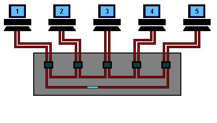
The heart of a LAN switch is a high-speed backplane and room for typically 4-32 plug in line cards, each containing one to eight connectors. Further each connector has a 10 Base-T twisted pair connection to a single host computer.
The transmitting station sends a standard frame to the switch. The plug-in card receives the frame and check for the destination address. If the address is of local stations the frame will be sent to local station otherwise the frame is sent over the high-speed back plane to the destination station's card. The backplane runs at over 1Gbps using proprietary protocol.
Collision prevention: There are two types of collision prevention; they are local on-card LAN and buffer-input port card.
In case of local on-card LAN, collision are detected and handled like any other CSMA/DC network- with retransmission using the binary backoff algorithm. Where as in buffer-input port card, the incoming frame-data are stored in RAM. Once a frame is completely received the card can then check to see if the frame is destines for another port on the same card, or for a distant port.
In the figure above the port in upper right hand corner is connected to a single station, but a 12-port hub. Even at the hub, the frames are transmitted to destination station in same way through collision detection and binary backoff. Successful frames are switched to the correct output line over the high speed backplane. If all the input ports are connected to hubs, rather than to individual stations, the switch just becomes an 802.3 to 802.3bridge.
IEEE802.4: Token bus
In this system, the nodes are physically connected as a bus, but logically form a ring with tokens passed around to determine the turns for sending. It has the robustness of the 802.3 broadcast cable and the known worst case behavior of a ring. The structure of a token bus network is as follows:
Token bus or 802.4 is more robust and reliable than 802.3 frames. The standard 802.4 is a linear or tree shaped cable onto which the stations are attached.
Network is a physical bus but a logical ring. The stations are numbered and are allowed to access the medium sequentially. If there are n stations, and packet transmission time is bounded to T, then the maximum waiting time is nT. Token bus MAC is simple and robust. Token bus is mostly used in automation systems.
Data is subdivided into four priority classes. Each station has four packet queues, one for each priority. When a station receives token, it is allowed to transmit certain fixed time. During that time it transmits packets in the decreasing order of priorities.
Frame Structure:
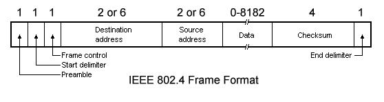
A 802.4 frame has the following fields:
Preamble: The Preamble is for synchronizing the receiver's clock.
Starting Delimiter (SD) and End Delimiter (ED): The SD and ED fields are used to mark frame boundaries. Both contain analog encoding of symbols other than 1 or 0 so that they cannot occur accidentally in the user data. Lengthy field is no more needed.
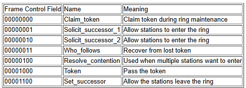
Frame Control (FC): FC is used to distinguish data frames from control frames. Data frames carries the frame's priority as well as a bit which the destination can set as an acknowledgement. For control frames, the Frame Control field is used to specify the frame type. Token passing and various ring maintenance frames are the allowed frame types.
Destination and Source Address: The Destination and Source address fields may be of 2 bytes (for a local address) or 6 bytes (for a global address).
Data: This is the actual data and it is of 8182 bytes when 2 byte addresses are used and 8174 bytes for 6 byte addresses.
Checksum: A 4-byte checksum of the data for error detection.
Ring Maintenance:
Whenever the first node on the token bus comes up, it sends a Claim_token packet to initialize the ring. If more than one station send this packet at the same time, there is a collision. Collision is resolved by a contention mechanism, in which the contending nodes send random data for 1, 2, 3 and 4 units of time depending on the first two bits of their address. The node sending data for the longest time wins. If two nodes have the same first two bits in their addresses, then contention is done again based on the next two bits of their address and so on.
Once the ring is set up, new nodes which are powered up may wish to join the ring. For this a node sends Solicit_successor_1 packets from time to time, inviting bids from new nodes to join the ring. This packet contains the address of the current node and its current successor, and asks for nodes in between these two addresses to reply. If more than one nodes respond, there will be collision. The node then sends a Resolve_contention packet, and the contention is resolved using a similar mechanism as described previously. Thus at a time only one node gets to enter the ring. The last node in the ring will send a Solicit_successor_2 packet containing the addresses of it and its successor. This packet asks nodes not having addresses in between these two addresses to respond.
A question arises that how frequently should a node send a Solicit_successor packet? If it is sent too frequently, then overhead will be too high. Again if it is sent too rarely, nodes will have to wait for a long time before joining the ring. If the channel is not busy, a node will send a Solicit_successor packet after a fixed number of token rotations. This number can be configured by the network administrator. However if there is heavy traffic in the network, then a node would defer the sending of bids for successors to join in.
There may be problems in the logical ring due to sudden failure of a node. What happens if a node goes down along with the token? After passing the token, a node, say node A, listens to the channel to see if its successor either transmits the token or passes a frame. If neither happens, it resends a token. Still if nothing happens, A sends a Who_follows packet, containing the address of the down node. The successor of the down node, say node C, will now respond with a Set_successor packet, containing its own address. This causes A to set its successor node to C, and the logical ring is restored. However, if two successive nodes go down suddenly, the ring will be dead and will have to be built afresh, starting from a Claim_token packet.
When a node wants to shutdown normally, it sends a Set_successor packet to its predecessor, naming its own successor. The ring then continues unbroken, and the node goes out of the ring.
The various control frames used for ring maintenance are shown below:
Priority Scheme:
Token bus supports four distinct priority levels: 0, 2, 4 and 6.
0 is the lowest priority level and 6 the highest. The following times are defined by the token bus:
THT: Token Holding Time. A node holding the token can send priority 6 data for a maximum of this amount of time.
TRT_4: Token Rotation Time for class 4 data. This is the maximum time a token can take to circulate and still allow transmission of class 4 data.
TRT_2 and TRT_0: Similar to TRT_4.
When a station receives data, it proceeds in the following manner:
It transmits priority 6 data for at most THT time, or as long as it has data.
Now if the time for the token to come back to it is less than TRT_4, it will transmit priority 4 data, and for the amount of time allowed by TRT_4. Therefore the maximum time for which it can send priority 4 data is= Actual TRT - THT - TRT_4
Similarly for priority 2 and priority 0 data.
This mechanism ensures that priority 6 data is always sent, making the system suitable for real time data transmission. In fact this was one of the primary aims in the design of token bus.
IEEE 802.5: Token Ring Network
Token Ring is formed by the nodes connected in ring format as shown in the diagram below.
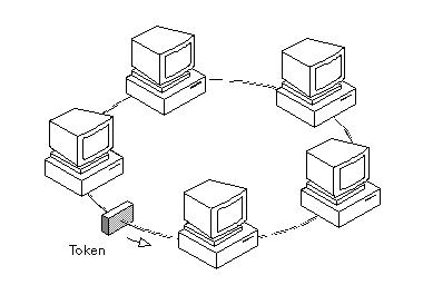
The principle used in the token ring network is that a token is circulating in the ring and whichever node grabs that token will have right to transmit the data. Whenever a station wants to transmit a frame it inverts a single bit of the 3-byte token which instantaneously changes it into a normal data packet. Because there is only one token, there can atmost be one transmission at a time.
Since the token rotates in the ring it is guarenteed that every node gets the token with in some specified time. So there is an upper bound on the time of waiting to grab the token so that starvation is avoided.
There is also an upper limit of 250 on the number of nodes in the network. To distinguish the normal data packets from token (control packet) a special sequence is assigned to the token packet. When any node gets the token it first sends the data it wants to send, then recirculates the token.
If a node transmits the token and nobody wants to send the data the token comes back to the sender. If the first bit of the token reaches the sender before the transmission of the last bit, then error situation araises. So to avoid this we should have:
propogation delay + transmission of n-bits (1-bit delay in each node ) > transmission of the token time
A station may hold the token for the token-holding time. which is 10 ms unless the installation sets a different value. If there is enough time left after the first frame has been transmitted to send more frames, then these frames may be sent as well. After all pending frames have been transmitted or the transmission frame would exceed the token-holding time, the station regenerates the 3-byte token frame and puts it back on the ring.

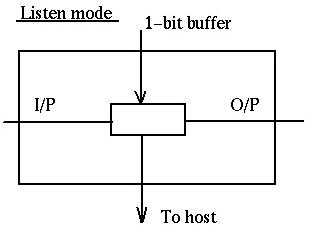
Modes of Operation
Listen Mode: In this mode the node listens to the data and transmits the data to the next node. In this mode there is a one-bit delay associated with the transmission.
Transmit Mode: In this mode the node just discards the any data and puts the data onto the network.
I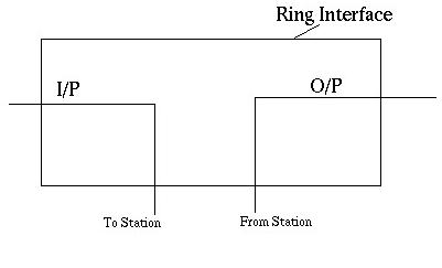
By-pass Mode: In this mode reached when the node is down. Any data is just bypassed. There is no one-bit delay in this mode.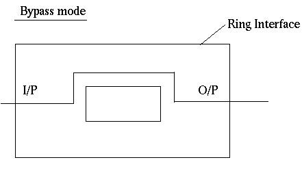
Token Ring Using Ring Concentrator
One problem with a ring network is that if the cable breaks somewhere, the ring dies. This problem is elegantly addressed by using a ring concentrator. A Token Ring concentrator simply changes the topology from a physical ring to a star wired ring. But the network still remains a ring logically. Physically, each station is connected to the ring concentrator (wire center) by a cable containing at least two twisted pairs, one for data to the station and one for data from the station. The Token still circulates around the network and is still controlled in the same manner, however, using a hub or a switch greatly improves reliability because the hub can automatically bypass any ports that are disconnected or have a cabling fault. This is done by having bypass relays inside the concentrator that are energized by current from the stations. If the ring breaks or station goes down, loss of the drive current will release the relay and bypass the station. The ring can then continue operation with the bad segment bypassed.
Removing Packet from the Ring
There are 3 possibilities-
1. The source itself removes the packet after one full round in the ring.
2. The destination removes it after accepting it: This has two potential problems. Firstly, the solution won't work for broadcast or multicast, and secondly, there would be no way to acknowledge the sender about the receipt of the packet.
3. Have a specialized node only to discard packets: This is a bad solution as the specialized node would know that the packet has been received by the destination only when it receives the packet the second time and by that time the packet may have actually made about one and half (or almost two in the worst case) rounds in the ring.
Thus the first solution is adopted with the source itself removing the packet from the ring after a full one round. With this scheme, broadcasting and multicasting can be handled as well as the destination can acknowledge the source about the receipt of the packet (or can tell the source about some error).
Token Format
The token is the shortest frame transmitted (24 bit)
MSB (Most Significant Bit) is always transmitted first - as opposed to Ethernet
| SD | AC | ED |
SD = Starting Delimiter (1 Octet)
AC = Access Control (1 Octet)
ED = Ending Delimiter (1 Octet)
Starting Delimiter Format:
| J | K | O | J | K | O | O | O |
J = Code Violation
K = Code Violation
Access Control Format:
| P | P | P | T | M | R | R | R |
T=Token
T = 0 for Token
T = 1 for Frame
When a station with a Frame to transmit detects a token which has a priority equal to or less than the Frame to be transmitted, it may change the token to a start-of-frame sequence and transmit the Frame
P = Priority
Priority Bits indicate tokens priority, and therefore, which stations are allowed to use it. Station can transmit if its priority as at least as high as that of the token.
M = Monitor
The monitor bit is used to prevent a token whose priority is greater than 0 or any frame from continuously circulating on the ring. If an active monitor detects a frame or a high priority token with the monitor bit equal to 1, the frame or token is aborted. This bit shall be transmitted as 0 in all frame and tokens. The active monitor inspects and modifies this bit. All other stations shall repeat this bit as received.
R = Reserved bits
The reserved bits allow station with high priority Frames to request that the next token be issued at the requested priority.
Ending Delimiter Format:
| J | K | I | J | K | I | I | E |
J = Code Violation
K = Code Violation
I = Intermediate Frame Bit
E = Error Detected Bit
Frame Format:
MSB (Most Significant Bit) is always transmitted first - as opposed to Ethernet
| SD | AC | FC | DA | SA | DATA | CRC | ED | FS |
SD=Starting Delimiter(1 octet)
AC=Access Control(1 octet)
FC = Frame Control (1 Octet)
DA = Destination Address (2 or 6 Octets)
SA = Source Address (2 or 6 Octets)
DATA = Information 0 or more octets up to 4027
CRC = Checksum(4 Octets)
ED = Ending Delimiter (1 Octet)
FS=Frame Status
Starting Delimiter Format:
| J | K | O | J | K | O | O | O |
J = Code Violation
K = Code Violation
Access Control Format
| P | P | P | T | M | R | R | R |
T=Token
When a station with a Frame to transmit detects a token which has a priority equal to or less than the Frame to be transmitted, it may change the token to a start-of-frame sequence and transmit the Frame.
P = Priority
Bits Priority Bits indicate tokens priority, and therefore, which stations are allowed to use it. Station can transmit if its priority as at least as high as that of the token.

M = Monitor
The monitor bit is used to prevent a token whose priority is greater than 0 or any frame from continuously circulating on the ring. if an active monitor detects a frame or a high priority token with the monitor bit equal to 1, the frame or token is aborted. This bit shall be transmitted as 0 in all frame and tokens. The active monitor inspects and modifies this bit. All other stations shall repeat this bit as received.
R = Reserved bits the reserved bits allow station with high priority Frames to request that the next token be issued at the requested priority
Frame Control Format:
| F | F | CONTROL BITS (6 BITS) |
FF= Type of Packet-Regular data packet or MAC layer packet
Control Bits= Used if the packet is for MAC layer protocol itself
Source and Destination Address Format:
The addresses can be of 2 bytes (local address) or 6 bytes (global address).
local address format:
| I/G (1 BIT) | NODE ADDRESS (15 BITS) |
alternatively
| I/G (1 BIT) | RING ADDRESS (7 BITS) | NODE ADDRESS (8 BITS) |
The first bit specifies individual or group address.
universal (global) address format:
| I/G (1 BIT) | L/U (1 BIT) | RING ADDRESS (14 BITS) | NODE ADDRESS (32 BITS) |
The first bit specifies individual or group address.
The second bit specifies local or global (universal) address.
local group addresses (16 bits):
| I/G (1 BIT) | T/B(1 BIT) | GROUP ADDRESS (14 BITS) |
The first bit specifies an individual or group address.
The second bit specifies traditional or bit signature group address.
Traditional Group Address: 2Exp14 groups can be defined.
Bit Signature Group Address: 14 grtoups are defined. A host can be a member of none or any number of them. For multicasting, those group bits are set to which the packet should go. For broadcasting, all 14 bits are set. A host receives a packet only if it is a member of a group whose corresponding bit is set to 1.
universal group addresses (16 bits):
| I/G (1 BIT) | RING NUMBER | T/B (1 BIT) | GROUP ADDRESS (14 BITS) |
The description is similar to as above.
Data Format:
No upper limit on amount of data as such, but it is limited by the token holding time.
Checksum:
The source computes and sets this value. Destination too calculates this value. If the two are different, it indicates an error, otherwise the data may be correct.
Frame Status:
It contains the A and C bits.
A bit set to 1: destination recognized the packet.
C bit set to 1: destination accepted the packet.
This arrangement provides an automatic acknowledgement for each frame. The A and C bits are present twice in the Frame Status to increase reliability in as much as they are not covered by the checksum.
Ending Delimiter Format:
| J | K | I | J | K | I | I | E |
J = Code Violation
K = Code Violation
I = Intermediate Frame Bit
If this bit is set to 1, it indicates that this packet is an intermediate part of a bigger packet, the last packet would have this bit set to 0.
E = Error Detected Bit
This bit is set if any interface detects an error.
Ring Maintenance
Each token ring has a monitor that oversees the ring. Among the monitor's responsibilities are seeing that the token is not lost, taking action when the ring breaks, cleaning the ring when garbled frames appear and watching out for orphan frames. An orphan frame occurs when a station transmits a short frame in it's entirety onto a long ring and then crashes or is powered down before the frame can be removed. If nothing is done, the frame circulates indefinitely.
Detection of orphan frames: The monitor detects orphan frames by setting the monitor bit in the Access Control byte whenever it passes through. If an incoming frame has this bit set, something is wrong since the same frame has passed the monitor twice. Evidently it was not removed by the source, so the monitor drains it.
Lost Tokens: The monitor has a timer that is set to the longest possible tokenless interval : when each node transmits for the full token holding time. If this timer goes off, the monitor drains the ring and issues a fresh token.
Garbled frames: The monitor can detect such frames by their invalid format or checksum, drain the ring and issue a fresh token.
The token ring control frames for maintenance are:
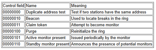
The monitor periodically issues a message "Active Monitor Present" informing all nodes of its presence. When this message is not received for a specific time interval, the nodes detect a monitor failure. Each node that believes it can function as a monitor broadcasts a "Standby Monitor Present" message at regular intervals, indicating that it is ready to take on the monitor's job. Any node that detects failure of a monitor issues a "Claim" token. There are 3 possible outcomes :
If the issuing node gets back its own claim token, then it becomes the monitor.
If a packet different from a claim token is received, apparently a wrong guess of monitor failure was made. In this case on receipt of our own claim token, we discard it. Note that our claim token may have been removed by some other node which has detected this error.
If some other node has also issued a claim token, then the node with the larger address becomes the monitor.
In order to resolve errors of duplicate addresses, whenever a node comes up it sends a "Duplicate Address Detection" message (with the destination = source) across the network. If the address recognize bit has been set on receipt of the message, the issuing node realizes a duplicate address and goes to standby mode. A node informs other nodes of removal of a packet from the ring through a "Purge" message. One maintenance function that the monitor cannot handle is locating breaks in the ring. If there is no activity detected in the ring (e.g. Failure of monitor to issue the Active Monitor Present token...) , the usual procedures of sending a claim token are followed. If the claim token itself is not received besides packets of any other kind, the node then sends "Beacons" at regular intervals until a message is received indicating that the broken ring has been repaired.
Phase Jitter Compensation :
In a token ring the source starts discarding all it's previously transmitted bits as soon as they circumnavigate the ring and reach the source. Hence, it's not desirable that while a token is being sent some bits of the token which have already been sent become available at the incoming end of the source. This behavior though is desirable in case of data packets which ought to be drained from the ring once they have gone around the ring. To achieve the aforesaid behavior with respect to tokens, we would like the ring to hold at least 24 bits at a time. How do we ensure this?
Each node in a ring introduces a 1 bit delay. So, one approach might be to set the minimum limit on the number of nodes in a ring as 24. But, this is not a viable option. The actual solution is as follows. We have one node in the ring designated as "monitor". The monitor maintains a 24 bits buffer with help of which it introduces a 24 bit delay. The catch here is what if the clocks of nodes following the source are faster than the source? In this case the 24 bit delay of the monitor would be less than the 24 bit delay desired by the host. To avoid this situation the monitor maintains 3 extra bits to compensate for the faster bits. The 3 extra bits suffice even if bits are 10 % faster. This compensation is called Phase Jitter Compensation.