IEEE 802.3
Brief background of IEEE802 standards for LAN and MAN
While connecting computers through networks we need to have set of rules/standards for the data to travel from one computer to other computer. The right example for this can be road traffic rules. It's self understood, why we need traffic rules while driving, in same sense for the data packets to travel from one computer terminal to other terminal they should also follow set of rules and regulations.
One such set of rules for the networking traffic to follow is IEEE802 standards. Its developed by IEEE (Institute of Electrical and Electronics Engineers, Inc.) The IEEE is the world's leading professional association for the advancement of technology. It's a non- profit organization offering its members immense benefits.
The standards such as IEEE 802 helps industry provide advantages such as, interoperability, low product cost, and easy to manage standards.
IEEE standards deal with only Local Area Networks (LAN) and Metropolitan Area Networks (MAN). See in the figure below, to know where exactly the IEEE802 standards are used in a OSI layer.

The IEEE 802 standards are further divided into many parts.
They are,
IEEE 802.1 Bridging (networking) and Network Management
IEEE 802.2 Logical link control (upper part of data link layer)
IEEE 802.3 Ethernet (CSMA/CD)
IEEE 802.4 Token bus (disbanded)
IEEE 802.5 Defines the MAC layer for a Token Ring (inactive)
IEEE 802.6 Metropolitan Area Networks (disbanded)
IEEE 802.7 Broadband LAN using Coaxial Cable (disbanded)
IEEE 802.8 Fiber Optic TAG (disbanded)
IEEE 802.9 Integrated Services LAN (disbanded)
IEEE 802.10 Interoperable LAN Security (disbanded)
IEEE 802.11 Wireless LAN & Mesh (Wi-Fi certification)
IEEE 802.12 demand priority (disbanded)
IEEE 802.13 Not Used
IEEE 802.14 Cable modems (disbanded)
IEEE 802.15 Wireless PAN
IEEE 802.15.1 (Bluetooth certification)
IEEE 802.15.4 (ZigBee certification)
IEEE 802.16 Broadband Wireless Access (WiMAX certification)
IEEE 802.16e (Mobile) Broadband Wireless Access
IEEE 802.17 Resilient packet ring
IEEE 802.18 Radio Regulatory TAG
IEEE 802.19 Coexistence TAG
IEEE 802.20 Mobile Broadband Wireless Access
IEEE 802.21 Media Independent Handoff
IEEE 802.22 Wireless Regional Area Network
Here we discuss most popular and key parts of above list
IEEE 802.3 Ethernet (CSMA/CD)
A method called Carrier Sense Multiple Access with Collision Detection (CSMA/CD) was used to send data over shared single co-axial cable connected to all computers on a network. In this method, the computer terminals (also called as stations) transmits the data over cable whenever the cable is idle, If more than one station transmit at same time and if they collide, the transmission will be stopped by such stations. They will wait for some random time and restart transmission.
The concept of sharing single cable or wire between multiple stations was used for first time in Hawaiian Islands. It was called ALOHA systems; built to allow radio communication between machines located at different places in Hawaiian Islands. Later Xerox PARC built a 2.94 mbps CSMA/CD system to connect multiple personal computers on a single cable. It was named as Ethernet.
Ethernet or IEEE802.3 standards only define MAC (Data link) and Physical layer of standard OSI model.
Don't confuse TCP/IP with Ethernet. TCP/IP defines Transport and network layers.
Wiring and cabling standards of 802.3
There are four cabling standards as per 802.3, each one has evolved over the time for their special advantages.
The four types of cables are,
1. 10Base5
2. 10Base2
3. 10Base-T
4. 10Base-F

The table below compares all four types of cables
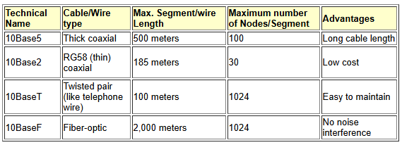
The 10 in the technical name refer to data speed of 10Mbits/sec.
"Link Integrity" and "Auto-partition" are part of the 10BaseT specification. This means that all network equipment claiming compliance with 10BaseT must support Link Integrity and Auto-partitioning.
10Base5
10 Base5 is also called as ThickNet or thick Ethernet. It uses RG-8 thick coaxial trunk cable, which looks like orange colored garden hose. The cable is tapered with taps called vampire taps in which a pin is carefully forced halfway into the cable's core. The connection can be made to the desired computer network interface card (NIC) from these vampire taps. ThickNet can travel 500 meters per segment, and it can have a maximum of 100 taps per segment. Each tap requires a minimum distance of 2.5 meters before the next tap and has a maximum drop distance of 50 meters. The cable must be terminated with a 50-ohm terminator resistor.
Due to its complex and slow nature 10Base5 is no more preferred. The severe drawback is entire line will fail for any single failure on the trunk. This cable can be termed as obsolete/outdated technology.
The one plus point of ThickNet is that, once it's up and running, it will continue to do so until you tell it otherwise. Although it is slow and unwieldy, 10Base5 technology is very reliable.
Here is the figure showing how the cables are connected to Network Interface Cards inside the computer using 10base5.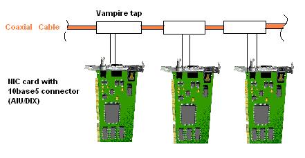
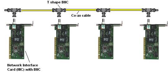
10Base2
10Base2 is not very different from 10 Base5. The most notable physical difference between 10Base2 and 10Base5 is the size of the co-axial cable. 10Base2 is thinner than the 10Base5 and so is called as ThinNet or thin Ethernet. Another difference is that 10Base2 is set up in a daisy chain. Daisy chain is a wiring scheme in which, for example, device A is wired to device B, device B is wired to device C, device C is wired to device D, et cetera.
10Base2 uses BNC connectors attached to a thin coaxial cable. The maximum segment length of 10Base2 is 185 meters, and the maximum number of devices per segment is 30.
10Base is also outdated/obsolete technology. In rare cases it could be deployed as a backbone for a network.
Here is the figure showing how the cables are connected to Network Interface Cards inside the computer using 10base5.
10Base-T
10Base-T is the most popular cabling method. Its also called Standard Ethernet, or twisted pair, 10Base-T works on a star topology connecting all computers to a hub. It is best used with Category 5 cable (so it can be upgraded to Fast Ethernet) and can have a maximum of three hubs daisy-chained together.
Since it is simple and cheap to implement it is most opted one. The specifications of Standard Ethernet include the following:
It uses RJ45 connectors on unshielded twisted-pair (UTP) cable.
The maximum cable length is 100 meters (before a repeater is needed).
The maximum number of devices per segment is 1,024 (although performance will become quite poor before that number is ever reached).
The 10Base-T standard is best employed within a LAN where cost is a factor-and speed and distance are not.
Link Integrity is concerned with the condition of the cable between the network adapter and the hub. If the cable is broken, the hub will automatically disconnect that port.
Auto partitioning occurs when an Ethernet hub port experiences more than 31 collisions in a row. When this happens, the hub will turn off that port, essentially isolating the problem.
10Base-F
In 10BaseF the twisted copper wires are replaced by a optical fiber. 10Base-F uses a higher quality cabling technology, multimode (or single-mode) fiber-optic cable, to transport data. The particular technology has two subdivisions that must be addressed: the newer 10Base-FL and 10BaseFOIRL.

Because it is older, the 10BaseFOIRL (Fiber-optic Inter-repeater Link) technology doesn't have quite the capabilities of the newer 10Base-FL. With 10BaseFOIRL, you have the following specs:
It's based on IEEE 802.3.
The segment length is 1,000 meters.
There are three sizes of duplex multimode fiber: 50-, 62.5-, or 100-micron. Of these three, 62.5-micron is the most common.
ST or SMA 905 connectors are used by 10BaseFOIRL.
It must be used in a star configuration.
AUI connectors have to be connected to fiber transceivers.
The much-improved 10Base-FL technology offers a different set of specs:
It's based on the 10Base-F IEEE 802.3 spec.
It's able to interoperate with FOIRL and is designed to replace the FOIRL specification.
The segment length is 2,000 meters (if exclusively using 10Base-FL).
The maximum number of devices per segment is two; one is the station and the other is the hub.
The maximum number of repeaters that may be used between devices is two.
NICs with standard AUI ports must use a fiber-optic transceiver.
The benefits of optical fiber are,
No radio or magnetic interference.
Transmissions are safe from electronic bugging,
Cable is extremely lightweight,
10Base-FL fiber-optic technologies are best implemented in long runs where reliability and security are critical.
Different types of cable topologies:
The four types of cable topologies are, linear, spine, tree, segmented.
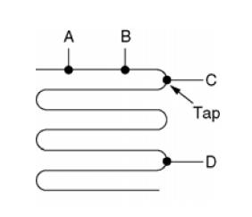
Linear: The linear topology is like a single cable running in all portions of building. The stations are connected to the cable through tapping.
Spine: It looks like our back one spinal cord, where multiple numbers of horizontal cables are connected to a vertical line through special amplifiers or repeaters.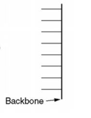
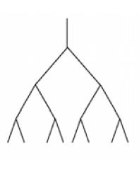
Tree: This is most general topology because a network with two paths between some pairs of stations would suffer from interference between the signals.
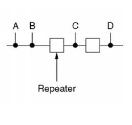
Segmented: Since each version of 802.3 has maximum cable length per segment, to allow larger networks, repeaters can connect multiple cables.
Manchester Encoding: The normal binary logics of one and zero are no more used to send data from one station to other station. The reason of not using plain binary signal is they cause ambiguities resulting in false interpretation of sent data. The major culprit is zero, where even no data is sent the receiver can assume it as zero.
So to clear out the ambiguity or to ensure proper interpretation of data, a coding technique called Manchester coding is employed in IEEE802.3 standards.
There are two of Manchester coding, they are simple Manchester coding and differential Manchester coding.
Summary
Each bit is transmitted in a fixed time (the "period").
A 0 is expressed by a low-to-high transition, a 1 by high-to-low transition (according to G.E. Thomas' convention -- in the IEEE 802.3 convention, the reverse is true).
The transitions which signify 0 or 1 occur at the midpoint of a period.
Transitions at the start of a period are overhead and don't signify data.
Manchester code always has a transition at the middle of each bit period and may (depending on the information to be transmitted) have a transition at the start of the period also. The direction of the mid-bit transition indicates the data. Transitions at the period boundaries do not carry information. They exist only to place the signal in the correct state to allow the mid-bit transition. Although this allows the signal to be self-clocking, it doubles the bandwidth requirement compared to NRZ coding schemes (or see also NRZI).
In the Thomas convention, the result is that the first half of a bit period matches the information bit and the second half is its complement.
If a Manchester encoded signal is inverted in communication, it is transformed from one convention to the other. This ambiguity can be overcome by using differential Manchester encoding.
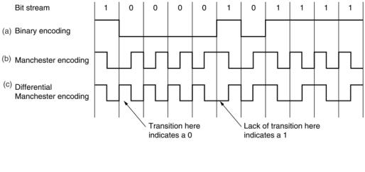
Differential Manchester Encoding Shown in above figure is a variation of basic Manchester encoding.
A '1' bit is indicated by making the first half of the signal equal to the last half of the previous bit's signal i.e. no transition at the start of the bit-time. A '0' bit is indicated by making the first half of the signal opposite to the last half of the previous bit's signal i.e. a zero bit is indicated by a transition at the beginning of the bit-time. In the middle of the bit-time there is always a transition, whether from high to low, or low to high. A reversed scheme is possible, and no advantage is given by using either scheme.
All 802.3 baseband systems use Manchester encoding due to its simplicity. The high signal is +0.85 Volts and low signal is -0.85 V giving a DC value of 0 volts.
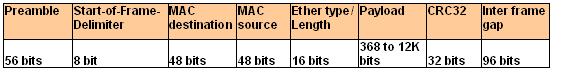
The 802.3 MAC sub layer protocol
The IEEE802.3 based Ethernet frame consists of preamble of 56 bit-size, start of the frame delimiter of 8bit size, destination address of 48 bit-size, sources address of 48 bit-size, type field to identify higher layer protocol of 16 bit-size, data field of variable bit-size, and frame check sequence field of 32 bit size.
The figure below explains better.
802.3 Ethernet MAC sub layer Protocol Minimum Frame Size
Longest segment = 500 meters
At most 4 repeaters
Maximum LAN length is 2500 m
Maximum round-trip time is 50µsec
10 Mbps implies 100 nsec / bit, 500 bits takes 50 µsec
802.3 uses 512 bits (64 bytes) as minimum frame size
The binary Exponential Backoff Algorithm
Exponential backoff is an algorithm that uses feedback to multiplicatively decrease the rate of some process, in order to gradually find an acceptable rate. It is often used in network congestion avoidance to help determine the correct sending rate. For example, a sender might send a message, set a timer to wait 0.25 seconds for an acknowledgment, and if none arrives, retransmit the message and wait 0.5 seconds for an acknowledgment. It will continue to retry until it receives an acknowledgement and will wait, 1s, 2s, 4s, 8s, etc. each time before retrying.
Time slots are defined to be 51.2µsec during contention period. After i collisions, backoff random number of intervals between 0 and 2i -1. i is bounded at 10. After 16 attempts, the sender quits
Basic Intuition used in the algorithm is,
----- Assume that number of contending stations is small until proven otherwise
----- If i were fixed at 1023, lots of unnecessary waiting
-----If i were fixed at 1, potential for unbounded waiting
The performance of Ethernet (802.3)
Here we evaluate the perfromance of 802.3 under the conditions of full load and constant load.
Metcalfe and Boggs - ignore binary exponential backoff and assume constant probability, p, of retransmission in each slot probability that one station acquires a slot, A, is
where
k = number of stations ready to transmit
p = probability that a station will retransmit
A is maximized when p is 1/k
When p is 1/k, A --> 1/e as k --> infinity
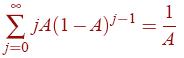
is the probability that the contention window is j slots
Mean number of slots per contention is:
Each slot is bounded by 2t, so the mean window size is bounded by
Assuming optimal p (p = 1/k), A= 1/e and
Let P be the mean transmission time / frame
Let
F = frame length
B = bandwidth
L = cable length
c = speed of light
P = F/B
and
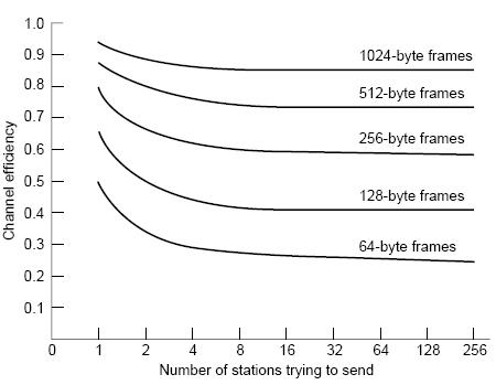
As BL increases, efficiency decreases
Here is the chart showing channel effeciency V/S Number of stations trying to send
.