MODULE - 8
SERIAL COMMUNICATION - Part 2
RS-232 interface
With the term "serial port" we will usually mean the hardware RS-232 and its signal levels, connections etc. because many of the modern devices still connect to serial port even after the development of many advanced technologies in serial communication systems. There may be many reasons like ease of debugging, cost effective, etc. Serial port is also termed as COM port.
RS-232 a standard is related to serial data communication between host systems, commonly known as Data Terminal Equipment, or DTE and a peripheral system termed, Data communication Equipment (also known as Data Circuit-Terminating Equipment) or DCE. To be more specific, the device that connects to the RS-232 interface is called a Data Communications Equipment (DCE) and the device to which it connects (e.g., the computer) is called a Data Terminal Equipment (DTE).
It was first introduced by the Electronics Industry Alliance (EIA) in the early 1960s and is commonly known as RS-232 (Recommended Standard 232). EIA-232 or RS-232 or RS-232 C is a complete serial communication protocol, which specifies signal voltages, signal timing, signal function, pin wiring, and the mechanical connections (i.e.: either 25-pin DB-25 or 9-pin DB-9). In 1987, the EIA released a new version of the standard and changed the name to EIA-232-D. And in 1991, the EIA teamed up with Telecommunications Industry association (TIA) and issued a new version of the standard called EIA/TIA-232-E. Many people, however, still refer the standard name as RS-232C, or just RS-232.
Let us now try to understand about the electrical, mechanical and functional interface characteristics of this standard.
Mechanical & functional characteristics:
We already know that the RS-232 standard supports two types of connectors - a 25-pin D-type connector (DB-25) and a 9-pin D-type connector (DB-9). The figure below shows the pin diagram of the connectors.
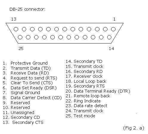
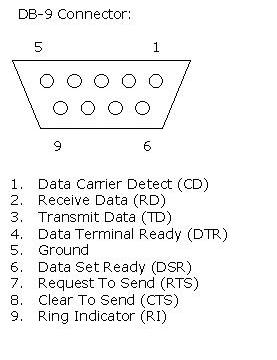
Although RS-232 specifies a 25-pin connector, this connector is often not used. Most applications do not require all the defined signals, so a 25-pin connector is larger than necessary. The most popular connector is the 9-pin DB9 connector, which provides the necessary signals for the serial communication in modem applications. So let us analyze the functions of each pins of the 9-pin RS-232 connector in comparison with that of DB-25. RS-232 signals have a direction (in or out) depending on whether they are with respect to a DTE or a DCE.
| DB-9Pin No: | DB-25 Pin No: | Signal | Type | Direction | Function |
| 1 | 8 | CD | Control | DCE to DTE | Determines whether the DCE is connected to a working phone line or not. (Only used in connection with modem) |
| 2 | 3 | TD | Data | DTE to DCE | Computer sends information to the DCE. |
| 3 | 2 | RD | Data | DCE to DTE | Computer receives information sent from the DCE. |
| 4 | 20 | DTR | Control | DTE to DCE | Computer tells the DCE that it is ready to communicate. Raised by DTE when powered on. In auto-answer mode raised only when RI arrives from DCE. |
| 5 | 7 | SG | Ground | -- | Signal Ground |
| 6 | 6 | DSR | Control | DCE to DTE | Modem tells the computer that it is ready to talk. Raised by DCE to indicate ready. |
| 7 | 4 | RTS | Control | DTE to DCE | Computer asks the modem if it can send information. Raised by DTE when it wishes to send. Expects CTS from DCE. |
| 8 | 5 | CTS | Control | DCE to DTE | Modem tells the computer that it can send information. Raised by DCE in response to RTS from DTE. |
| 9 | 22 | RI | Control | DCE to DTE | Set when incoming ring detected - used for auto-answer application. DTE raises DTR to answer. (Only used in connection with modem) |
| -- | 12, 13, 14, 16, 19, 24 | -- | -- | -- | Only needed if second channel being used. |
| -- | 15 | DB | Timing | DTE to DCE | Transmit clock. (Used in Synchronous mode only) as Transmitter Signal Element Timing. |
| -- | 17 | DD | Timing | DCE to DTE | Receive clock (used in synchronous mode only) as Receiver Signal Element Timing. |
| -- | 18 | L L | Control | DTE to DCE | Local Loop back |
| -- | 21 | RL/SQ | Control | DTE to DCE | Signal quality detector /Remote Loop back |
Electrical characteristics:
RS-232 defines the purpose, signal timing and signal levels for each line. It's an Active LOW voltage driven interface i.e. it transmits positive voltage for a 0 bit, negative voltage for a 1. And the output signal level usually swings between +12 V and -12 V. The high level is defined as between +5V to +12V, and a low level is defined as between -5V and -12V. With 2V of noise margin, a high level for the receiver is defined as between +3V to +12V, and a low level is between -3V to -12V. The signal voltage between +3 V and -3V, called "dead area" is designed to absorb line noise. A low level is defined as logic 1 and is referred to as "marking." Similarly, a high level is defined as logic 0 and is referred to as "spacing." The following figure illustrates the logic level.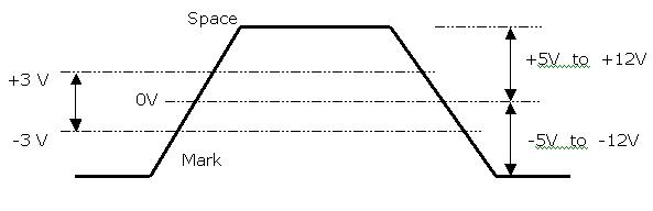

Note:
In the embedded system, if the device communicates at TTL level, the connection between the embedded system and external device is simple. But if the device needs RS232 level signaling, we will have to insert a RS-232 Line Driver/Receiver between the processor and the device. Most of the devices used nowadays need three wires, i.e. Transmit Data, Receive Data and Signal Ground. No need of hardware flow control signal. This simplifies the hardware connection as well as the software design. The figure below shows how the data look like for ASCII-A .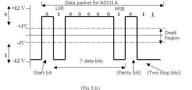
Connections & signal flow control:
Flow control is the process of managing the rate of data transmission between two nodes to prevent a fast sender from over running a slow receiver. For example, as DTE to DCE speed is a few times faster than DCE to DCE speed, the PC can send data to the modem at a higher rate. That means in this connection sooner or later the data may be lost because of the buffers overflow, so the control of data flow should be realized.
Flow control mechanisms can be classified by whether or not the receiving node sends feedback to the sending node. That is through a "handshake", an exchange of characters between a transmitter and a receiver is used to postpone transmission until the receiver is ready to receive the data.
This character flow control is of two main types: Hardware & Software
Software Flow Control:
One example is "Xon/Xoff".Two characters Xon and Xoff are used here control the data flow. Xon is usually a 17 character, and Xoff is a 19 character. The modem will only have a small buffer. As when the computer fills it, the modem sends a Xoff character to inform the computer about data transfer termination. As soon as the modem empties the most of the memory for data, it will send the Xon character to the computer and to start the data transfer again. The main advantage of this type of data flow control is that it doesn't need any other wires as the characters are sent via TD/RD lines. But if the connection is slow, every character needs 10 bits, which can reduce the connection speed.
Hardware Flow Control:
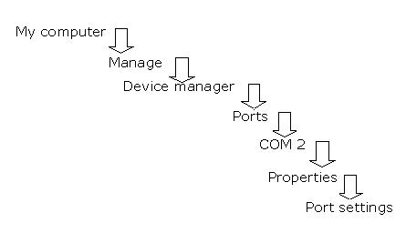
Most serial communications uses software Flow Control, but there is an alternative: hardware handshaking. Hardware flow control is also known as RTS/CTS flow control. To realize this control two additional wires (RTS & CTS) in the sequential cable are used. This results in increasing the data transmission rate, as no time is spent for Xon-Xoff characters transmission. The flow control mode (whether Xon-Xoff or Hardware) can be selected as indicated below:
Here the transmission activates the Request To Send (RTS) line when the computer is ready to send data .If the modem has a free buffer for this data, it activates the Clear to Send (CTS) line in response and the computer starts sending data. If the modem lacks free memory, it won't activate the CTS.
One of the main drawbacks of hardware handshaking is that some modems cannot deal correctly with binary data streams that contain characters, which look like DC1/DC3. Hardware handshaking is also known as Out-of-Band flow control, because the signals are generated and observed outside the flow of the data.
Care must be taken when enabling hardware handshaking. Both parties have to agree and be compatibly configured before you start. Software flow-control is re-active. Things proceed normally until one party says, "Stop!" But the hardware flow-control is pro-active. You do not start transmitting until you receive the Go signal. If you never get it, you never start. Fortunately, with most modems the hardware handshake rules are not turned ON until a connection has been established.
Let us now try to understand how a serial port can be connected to another one.
Null Modem connection:
The serial communication standards show the use of DTE/DCE communication, the way a computer should communicate with a peripheral device like a modem. But in Null modem connection, the PCs are connected back-to-back with cables, each acting as a DTE, which means there is no DCE in this case. This type of connection finds many uses nowadays. The null modem can be configured in many ways using the number of signal lines available. In most situations, the original modem signal lines are reused to perform some sort of handshaking.
Handshaking has many advantages. It can increase the maximum allowed communication speed because then the computer will be able to control the flow of information. In null modem connection without "flow control", the communication may be possible only at the speed at which the receiving side can handle the amount of data.
Before we talk about the Null-modem connections, let us try to refresh our knowledge about the different types of flow control signals used in RS-232. The first two flow control pins are known as RTS (request to send), an output signal from the DTE, which obviously comes as the input for the DCE and CTS (clear to send), which come as the answering signal from the DCE side. Before sending a character, the DTE asks permission by setting its RTS output. No information will be sent until the DCE grants permission by making the CTS line high.
The other two flow control signals, DTR, data terminal ready and DSR, data set ready are used to signal the status of one communication side to the other. The DTE uses the DTR signal to signal that it is ready to accept information, whereas the DCE uses the DSR signal for the same purpose. The last flow control signal present in DTE/DCE communication is the CD carrier detect. It is not used directly for flow control, but indicates the existence of a communication link between two modem devices.
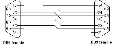
a) Without handshaking:
This is the simplest and commonly used way of connection, which is shown in the following figure. As you can see, only the data lines and signal ground are cross-connected. All other pins have no connection, which means there is no handshaking.
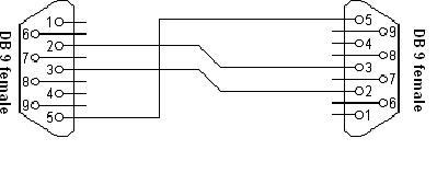
This type of connection can be used to communicate with devices, which do not have modem control signals.
b) Loop back handshaking:
Before going to talk about loop-back handshaking, let us try to point-out the issues associated with the simple null modem without handshaking.
1. Suppose the software on both sides of the communication is well structured. What happens if either the DCE or DTE checks for the DSR or CD inputs? These signal levels will never go high, as it is kept not connected, which may cause problems.
2. Same thing may happen for the RTS/CTS handshaking sequence also. The RTS output is set high by the DTE and then waits for a ready signal to be received on the CTS line. This may enhance the possibility for the software to hang because no physical connection is present to either CTS line.
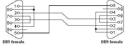
To overcome this problem and still be able to use a cheap null modem we can use the connection layout shown above termed as Null modem with loop back handshaking, which make the well defined & structured software to think that there is some handshaking available (even though it is a fake one).

c) Partial handshaking:
The problems associated with the loop back handshaking are as follows.
1. The DSR signal input indicates that the other side is ready for communication. But the line is connected back to the DTR output of the same side, which means, that the software doesn't see the ready signal of the other device, but its own. This may create problem for the proper communication. The same thing happens in the case of the CD input.
2. Again this also has no functional enhancements over the simple connection. There is no way both devices can control data flow, other than by using XON/XOFF handshaking.
3. If the software is designed for using hardware flow control (in the case of loop-back handshaking) there is a chance for data loss. When data speeds reach the limit the receivers can handle, communication may stop immediately without any reason.
In the case of CTS/RTS of this type connection, the software may not hang-up because the CTS input on the same connector side is receiving clearance immediately when the RTS is set high.
Both the simple null modem connection and the null modem with loop back handshaking have no provisions for hardware flow control. If a condition comes that the hardware flow control is necessary the null modem with partial handshaking can be used.
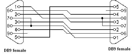
d) Full handshaking:
The software, which uses only the RTS/CTS protocol for the flow control, cannot go for the partial handshaking null modem connection. The solution for this is the use of "full handshaking". This is the most expensive null modem connection. In this mode of connection, all the pins, except RI and CD are used. The main advantage of this connection is that there are two signaling lines in each direction. Both the RTS and DTR are there to send flow control information to the other device. This makes it possible to achieve very high communication speeds, provided that the software has been designed for it.
Virtual null modem
This is also a type of communication method to connect two computer applications directly using virtual serial port. Unlike null modem cable, virtual null modem is a software solution, which emulates hardware null modem in computer. All features of hardware null modem can be made available in virtual null modem as well. Some of the main advantages of this are:
1. No serial cable is needed.
2. Serial port of computer is not used.
3. Unlimited number of virtual connections is possible.
4. Transmission speed of serial data is limited only by computer performance
5. Virtual connection over network or Internet is possible. So Unlimited distance of communication can be achieved.