Important Note: EE Herald has now (from October 2012) published embedded systems design practice using latest kits from ST Microelectronics and NXP Semiconductors based on the popular ARM Cortex M0 processor core. The old AME 51 kit for which the sample program explained from next paragraph in this module is not avaialable in the market now. We strongly recommend not to use AME 51 kit, instead read our module3b based on ARM Cortex M0 powered ST MIcro's Disocvery kit and and module3a based on ARM Cortex M0 powered NXP LPCXpresso kit to get into practical learning of embedded systems programming. Sample program for ST kit is available at esmod4bsample and esmod6b and sample program for NXP kit is available at esmod4asample and esmod6a.
MODULE - 6
Sample Program 2: Display decimal numbers from 0-9 in the seven segment display.
As we learn the basic idea about programming and how to run and execute it in the previous module (module -4), its time to move on to next level of programming. Instead of turning ON & OFF an LED, let us use the seven segment display device in the kit to display or count the numbers from 0 to 9.
Before going into programming steps, let us have an idea about the seven segment display and its connectivity to the driver & the MCU unit.
The following fig (Fig 6.a) shows various elements of a 7 - segment display and how it is connected to different pots of the MCU GPIO (General Purpose Input and Output). Please note segment A- F are connected to one port(PF) and elements G and DP are connected to other port (PD)
.
Fig 6.a
For circuit details download the circuit diagram file. Though reading into circuit is little stressful but gives more insight into how the ports are connected.
The display used is a common anode type RED display unit , which is connected to the MCU through a Low-Voltage Octal Bus Buffer (inverted), TC74LCX240F.
So now what we have do is, to find out the Hexadecimal code word for each number (from 0 to 9) to get displayed on the 7-segment LED display unit.
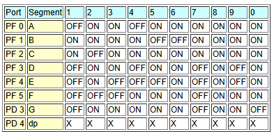
Chart 1
The above chart (chart 1) provides the information on which output lines/pins to be made high or low to display the corresponding numbers. We have not used dp (decimal point) segment and so is the status given as 'X' meaning don't care.
Now, let us figure out the hexadecimal code for each number.
For example let us take the number "2". From the chart given above, it can be understood that, to display 2, we need to make a, b, d, e & g segments of the display "HIGH" and the remaining segments "LOW".
Thus the GPIO output registers PF & PD should hold the data values as shown below.
X - Don't care
Here let's assume to substitute X with 0 (zero). The hexadecimal equivalent of "011011" is "1B" and that of "001000" is "08". So to display the digit "2" we need to load 1B to the register of the port PF and 08 to the register of the port PD.
Similarly we can find out the hexadecimal equivalent code for each digit to be displayed.
Once we got the Hexadecimal code for each number, it is time to move to the programming section. Here are the basic steps to be followed.
- As we did in the Module-4 , copy the TestLED directory as COUNTER. Now you would have COUNTER folder as well in "C:\ame51gnu\Examples\674051" directory
- Rename theTestLED.c in this directory as counter.c
- Open the counter.c file with "Notepad++" or any other text editor and delete all the content and insert the following code in this file
int main(void)
{
int i;
volatile unsigned char * ModeRegister1;
volatile unsigned char * OutputRegister1;
volatile unsigned char * ModeRegister2;
volatile unsigned char * OutputRegister2;
ModeRegister1 = 0xB7A05008; // PF GPIO mode register address in Hex
OutputRegister1 = 0xB7A05000; // PF GPIO output register address in Hex
ModeRegister2 = 0xB7A03008; // PD GPIO mode register address in Hex
OutputRegister2 = 0xB7A03000; // PD GPIO output register address in Hex
*ModeRegister1 =0x00FF; // Configure Port F bit 0 as output
*ModeRegister2 =0x00FF; // Configure Port D bit 0 as output
while (1)
{
*OutputRegister1 = 0x003F; // Display 0
*OutputRegister2 = 0x0000; // Display 0
for (i=0; i<1000000; i++); //Delay
*OutputRegister1 = 0x0006; // Display 1
*OutputRegister2 = 0x0000; // Display 1
for (i=0; i<1000000; i++); //Delay
*OutputRegister1 = 0x001B; // Display 2
*OutputRegister2 = 0x0008; // Display 2
for (i=0; i<1000000; i++); //Delay
*OutputRegister1 = 0x000F; // Display 3
*OutputRegister2 = 0x0008; // Display 3
for (i=0; i<1000000; i++); //Delay
*OutputRegister1 = 0x0026; // Display 4
*OutputRegister2 = 0x0008; // Display 4
for (i=0; i<1000000; i++); //Delay
*OutputRegister1 = 0x002D; // Display 5
*OutputRegister2 = 0x0008; // Display 5
for (i=0; i<1000000; i++); //Delay
*OutputRegister1 = 0x003D; // Display 6
*OutputRegister2 = 0x0008; // Display 6
for (i=0; i<1000000; i++); //Delay
*OutputRegister1 = 0x0007; // Display 7
*OutputRegister2 = 0x0000; // Display 7
for (i=0; i<1000000; i++); //Delay
*OutputRegister1 = 0x003F; // Display 8
*OutputRegister2 = 0x0008; // Display 8
for (i=0; i<1000000; i++); //Delay
*OutputRegister1 = 0x0027; // Display 9
*OutputRegister2 = 0x0008; // Display 9
for (i=0; i<1000000; i++); //Delay
}
}
5. Now compile and run the program by following the same steps as given in module -4.

6. Follow the procedures to load the program into the board as mentioned in module-4 or read this user manual.
Now you should see the 7-segment LED display, counting from 0 to 9 and repeats the same.
You might have already got an idea about the ARM chipset used in this kit, different ports, bits, different type of modes in which it can operate (or can be configured), and how to use the mode register & output register to make the MCU to work according to our needs. Same kind of configuration is done in this sample program also, except the registers used are PF & PD.
Sample Program 3: Simultaneously display decimal numbers from 0-9 in the seven segment display and lighting the three LEDs available on the board/kit.
The following fig (Fig 6.b) shows the connectivity of the 3 LEDs (Green, Red & Yellow) to the Micro controller ports.

Fig 6.b
Hope you remember that we used the port PE in the sample program in module 4.
Same port is used here too to connect the three LEDs to the MCU.
And also, as you saw in the previous sample program in this module (module 6), the ports PF & PD are used for the 7-segment display unit to get connected to the MCU.
So let us do it in a different way. Make the green LED to glow when the 7-segment displays digits '2' and '4', both green & yellow LEDs to glow while displaying '5', '6' and '7' and all the three LEDs to glow while displaying '8' and '9' on the 7-segment display.
So let us configure the output register of the port PE for the three LED to work along with the 7-segment display unit.
As you can see in the fig 6.b, the port bitsPE0, PE1 & PE2 are used to drive the red, Yellow & green LEDs respectively. And remember they are wired (in the kit) as "active low".
| Bit | PE6 | PE5 | PE4 | PE3 | PE2 | PE1 | PE0 |
| Data | X | X | X | X | 0 | 0 | 0 |
Suppose we want to glow the three LEDs at a time. For this, all the three bits PE0, PE1 & PE2
are made Low (0) (bits PE3 to PE6 kept as "Dontcare" in this case)
Its clear that the hexadecimal code to display all the three LEDs is 00 and to make all of them OFF, the code is 07.
Now its time to focus on the program code. Let us change the previous program as show below.
int main(void)
{
int i;
volatile unsigned char * ModeRegister1;
volatile unsigned char * OutputRegister1;
volatile unsigned char * ModeRegister2;
volatile unsigned char * OutputRegister2;
volatile unsigned char * ModeRegister3;
volatile unsigned char * OutputRegister3;
ModeRegister1 = 0xB7A05008; // PF GPIO mode register address in Hex
OutputRegister1 = 0xB7A05000; // PF GPIO output register address in Hex
ModeRegister2 = 0xB7A03008; // PD GPIO mode register address in Hex
OutputRegister2 = 0xB7A03000; // PD GPIO output register address in Hex
ModeRegister3 = 0xB7A04008; // PE GPIO mode register address in Hex
OutputRegister3 = 0xB7A04000; // PE GPIO output register address in Hex

*ModeRegister1 =0x00FF; // Configure Port Fbit 0 as outuput
*ModeRegister2 =0x00FF; // Configure Port D bit 0 as outuput
*ModeRegister3 =0x00FF; // Configure Port E bit 0 as output
while (1)
{
*OutputRegister1 = 0x003F; // display 0
*OutputRegister2 = 0x0000; // display 0
*OutputRegister3 = 0x0007; // all the three LEDs OFF
for (i=0; i<1000000; i++); //Delay
*OutputRegister1 = 0x0006; // Display 1
*OutputRegister2 = 0x0000; // display 1
*OutputRegister3 = 0x0007; // all the three LEDs OFF
for (i=0; i<1000000; i++); //Delay
*OutputRegister1 = 0x001B; // display 2
*OutputRegister2 = 0x0008; // display 2
*OutputRegister3 = 0x0003; //Green LED ON
for (i=0; i<1000000; i++); //Delay
*OutputRegister1 = 0x000F; // display 3
*OutputRegister2 = 0x0008; // display 3
*OutputRegister3 = 0x0003; //Green LED ON
for (i=0; i<1000000; i++); //Delay
*OutputRegister1 = 0x0026; // display 4
*OutputRegister2 = 0x0008; // display 4
*OutputRegister3 = 0x0003; //Green LED ON
for (i=0; i<1000000; i++); //Delay
*OutputRegister1 = 0x002D; // display 5
*OutputRegister2 = 0x0008; // display 5
*OutputRegister3 = 0x0001; // Green & Red LEDs ON
for (i=0; i<1000000; i++); //Delay
*OutputRegister1 = 0x003D; // display 6
*OutputRegister2 = 0x0008; // display 6
*OutputRegister3 = 0x0001; // Green & Yellow LEDs ON
for (i=0; i<1000000; i++); //Delay
*OutputRegister1 = 0x0007; // display 7
*OutputRegister2 = 0x0000; // display 7
*OutputRegister3 = 0x0001; // Green & Yellow LEDs ON
for (i=0; i<1000000; i++); //Delay
*OutputRegister1 = 0x003F; // display 8
*OutputRegister2 = 0x0008; // display 8
*OutputRegister3 = 0x0000; //green, Yellow, & Red LEDs ON
for (i=0; i<1000000; i++); //Delay
*OutputRegister1 = 0x0027; // dis9
*OutputRegister2 = 0x0008; // dis9
*OutputRegister3 = 0x0000; //green, Yellow, & Red LEDs ON
for (i=0; i<1000000; i++); //Delay
}
}
Now what you have to do is just edit the "counter.c" file in the COUNTER folder and alter the program as shown in the above code, or copy this program entirely to the counter.c file after deleting the previous code . compile and run the code as explained along with the previous sample programs. Now you can see the LED getting on in the planned sequence while the seven segment is displaying 0 to 9.
Now its times to write your own program?
Write an easy program to display hexadecimal numbers F to 0 in decremental order.
ABOUT THIS COURSE:
Totally EEHerald plan to bring 12 modules. You can be assured of completing basic course in Embedded Systems after studying and practicing exercises in all the modules. We will give priority to programming and serial communications (SPI, USB, CAN etc..) part. To receive a copy of total course syllabus, please email to us.
This free tutorials on embedded systems is prepared by embedded professionals with more than10 years of industrial experience, however we want your feedback on this course content; please email your questions, suggestions and comments to editor@eeherald.com. Your questions on present modules will be answered in the revised modules. We may change the course content based on the majority of your requests and feedbacks.
Please let your friends know about this course, we request you to email this link to your friends and colleagues who are interested in embedded system.