Display of numerics 0 to 9 on a 7-segment LED display
In this module a very-simple c program/code to display 0-9 on a 7-segment LED display using STM32F0-DISCOVERY microcontroller (MCU) board is explained.
Hardware requirements along with the board:
1. Seven segment display (Common Cathode)
2. 8-Resistors (3.3 Kilo ohms)
3. connecting wires
4. General purpose printed circuit board or a breadboard
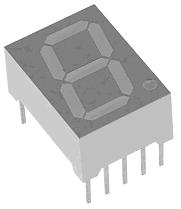
Seven segment display:
Seven segment LED is device having seven light emitting diodes with either anode terminals (common anode ) or cathode terminals connected together to form a number '8' pattern as shown below in the picture.
To know more on 7-segment LED visit: 7 segment
and Node 7
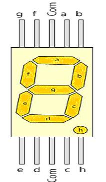
To use them you should know the pin configuration of the commercially available displays. As you must have guessed these displays should have nine pins( one for each segment + decimal point +common) but the available modules have two pins for common ground. They are internally connected. So they have total of 10 pins (see the picture below).
A 7-Segment display has 7-segments/pins named as a, b, c, b, e, f, g for forming the '8' pattern and and another segment/pin called 'h' for DP (decimal point) along with two extra pins for GND (in case of common cathode).
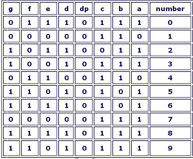
To display numbers in seven-segment display, it is necessary to define the control signals
Below table shows the segment control for characters 0-9 as required for displaying numbers.
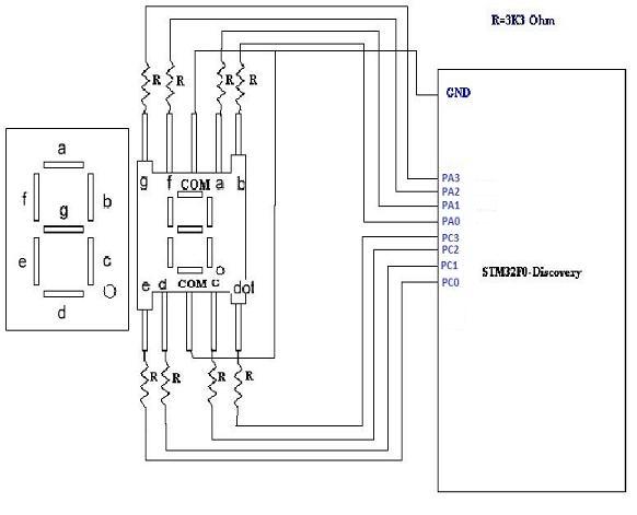
Circuit diagram of 7-Segment Display Interfacing to ARM Cortex M0 microcontroller powered STM32F0 board:
The below circuit connects 7-Segment display with port C and port A of microcontroller.

Programming:
The sample c-program/code below continuously display digits 0-9 on seven-segment display and then repeating the sequence. The text below in dark-red color is the sample code:
#include "main.h"
#include "stm32f0xx_conf.h"
uint32_t TickValue=0;
//-----------------------------
// Function Name : Init _GPIO pins
// Description : pins ,port clock & mode initialization.
//----------------------------
void Init_GPIO(void)
{
/* GPIO config */
GPIO_InitTypeDef GPIO_InitStructure;
/* GPIOA GPIOB clock enable */
RCC_AHBPeriphClockCmd(RCC_AHBPeriph_GPIOA | RCC_AHBPeriph_GPIOC, ENABLE);
/* Configure 8 ,9 PINS as input floating */
GPIO_InitStructure.GPIO_Pin =GPIO_Pin_0 | GPIO_Pin_1 | GPIO_Pin_2 | GPIO_Pin_3 ;
/* Configure PORT clock speed */
GPIO_InitStructure.GPIO_Speed = GPIO_Speed_10MHz;
/* Configure PORT mode as input */
GPIO_InitStructure.GPIO_Mode = GPIO_Mode_OUT;
/*configure PINS to output pushpull mode*/
GPIO_InitStructure.GPIO_OType = GPIO_OType_PP;
/* Above all GPIO instructions apply to port "C"*/
GPIO_Init(GPIOC, &GPIO_InitStructure);
/* Configure 8,9,10,11,12,13 pins as input floating */
GPIO_InitStructure.GPIO_Pin = GPIO_Pin_0 | GPIO_Pin_1 | GPIO_Pin_2 | GPIO_Pin_3 ;
;
/* Configure PORT clock speed */
GPIO_InitStructure.GPIO_Speed = GPIO_Speed_10MHz;
/* Configure PORT mode as input */
GPIO_InitStructure.GPIO_Mode = GPIO_Mode_OUT;
/*configure PINS to output pushpull mode*/
GPIO_InitStructure.GPIO_OType = GPIO_OType_PP;
/* Above all GPIO instructions apply to port "B"*/
GPIO_Init(GPIOA, &GPIO_InitStructure);
}
void TimingDelay_Decrement(void)
{
TickValue--;
}
//----------------------
// Function Name : delay_ms
// Description : delay for some time in ms unit(accurate)
// Input : n_ms is how many ms of time to delay
//---------------------
void delay_ms(uint32_t n_ms)
{
// SysTick interrupt each 1000 Hz with HCLK equal to 32MHz
// - 30 to compensate the overhead of this sub routine
SysTick_Config(8000*PLL_MUL_X - 30);
// Enable the SysTick Counter
TickValue = n_ms;
while(TickValue == n_ms)
;
// SysTick interrupt each 1000 Hz with HCLK equal to 32MHz
SysTick_Config(8000*PLL_MUL_X);
while(TickValue != 0)
;
}
/****************************
* Function Name : main
* Description : Main program.
*****************************/
int main(void)
{
Init_GPIO(); //calling a function
while(1)//infinite loop
{
/*ODR bits can be individually set and reset */
//for displaying 0
GPIOA->ODR = 0x0007;
GPIOC->ODR = 0x0007;
delay_ms(1000);
//for displaying 1
GPIOA->ODR = 0x0001;
GPIOC->ODR = 0x0004;
delay_ms(1000);
//for displaying 2
GPIOA->ODR = 0x000B;
GPIOC->ODR = 0x0003;
delay_ms(1000);
//for displaying 3
GPIOA->ODR = 0x000B;
GPIOC->ODR = 0x0006;
delay_ms(1000);
//for displaying 4
GPIOA->ODR = 0x000D;
GPIOC->ODR = 0x0004;
delay_ms(1000);
//for displaying 5
GPIOA->ODR = 0x000E;
GPIOC->ODR = 0x0006;
delay_ms(1000);
//for displaying 6
GPIOA->ODR = 0x000E;
GPIOC->ODR = 0x0007;
delay_ms(1000);
//for displaying 7
GPIOA->ODR = 0x0003;
GPIOC->ODR = 0x0004;
delay_ms(1000);
//for displaying 8
GPIOA->ODR = 0x000F;
GPIOC->ODR = 0x0007;
delay_ms(1000);
//for displaying 9
GPIOA->ODR = 0x000F;
GPIOC->ODR = 0x0006;
delay_ms(1000);
}
}
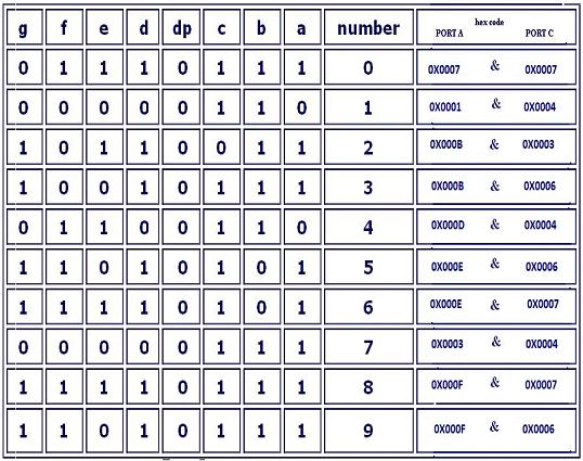
Please refer the table below for the hexa-decimal code required at the output port-2 and port-3 for displaying a particular number on the 7-segment.
Click below to visit next and other embedded system course modules:
Module 5C: ARM Cortex M0 features and details -1
Module 7: Serial communication concepts -1

Module 9: Controller Area Networking (CAN)
Module15: SRAM memory interface
Module16: Flash memory interface
Module17: LCD display panel interface
Module18: Touch pane interface
Module19: Audio/video interface
Previous Modules
Module 1: Introduction to Embedded Systems: Definition, application and future.
Module 2: Microprocessor, Microcontroller, MCU Manufacturers, introduction to programming.
Module 3b: Installation of ARM Cortex M0 based STM32F0 Discovery kit from ST Microelectronics and sample code