With the 32- bit micorcontrollers becoming popular and also the kits/boards available at affordable prices, we at EE Herald bringing you new modules on embedded systems design practice. The idea is to provide you the inexpensive 32-bit MCU based latest hardware boards. We have selected ARM Cortex M0 based boards: LPCXpresso development board from NXP Semiconductors and STM32F0 Discovery from ST MIcroelectronics. Both the boards we have suggested here are available in India. Below is the installation and program execution guide for STM32F0 Discovery from ST MIcroelectronics. STM32F0 board is supported by 3rd party software development environment from IAR.
1. REQUIREMENTS
1.1 PC system requirements for installing IAR software supporting STM32F0 Discovery kit installation
Operating System: Windows PC (2000, XP, Vista, Windows 7).
System RAM: 512 MB minimum (1 GB recommended).
Hard Disk: 20 Gb of available space.
Internet Connection: High-speed internet is recommended to download and register the software .
Slow old systems are not recommended
1.2 Hardware requirements
1. STM32F0-Discovery development board.
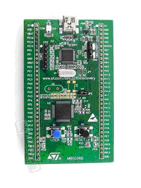
To buy this kit or to learn more visit ST website at 250863
The cost of this kit 9.9 US$
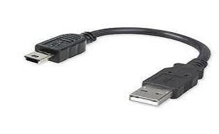
2. USB 2.0 A/Mini-B cable
1.3 IDE software installation and running the sample program:
1. You got to download the file EWARM-KS-CD-6403.exe of size 812MB from IAR website, First step here is to visit IAR and create account using your email id.
2. License Number AND License Key will be sent to your e-mail. And Download option is also sent to email id.
3. As per the download instructions, download the software from IAR website. It takes 2-3 hours with average broadband speed.
4. Save License Number and License Key, while installing it is required.
2. Installation process:
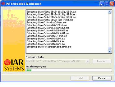
Double click the EWARM-KS-CD-6403.exe file and follow the instructions.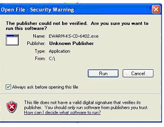
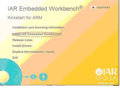
3.After installation is complete, automatically below screen will pop-up
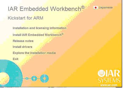
4. Click on the text "Install Drivers"

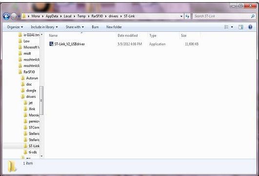
You will be taken to a folder containing list of drivers for microcontrollers. Click on the sub-folder 'ST-Link' and you will see a file named "ST-Link_V2_USBdriver.exe". select this file to install the driver.
Follow the steps suggested by the installation program.
5.Next install IAR Embedded Workbench also.
While installing it will ask for License Number and License Key, enter that data. The installation takes long time, wait for some time (in slow systems it even takes an hour).
Running a sample program:
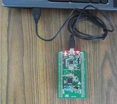
Before running your application, you should establish the connection with the STM32F0DISCOVERY board with the computer (USB port of desktop/laptop)as shown in the picture below.
Debugging/running sample project
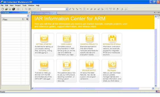
1.Open IAR Embedded Workbench IDE tool.
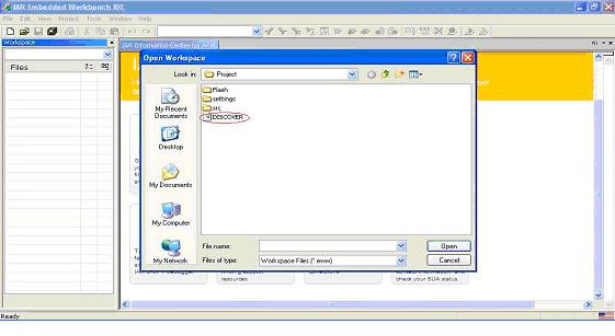
2. Then open File-> Open-> Workspace

3. Then select" C-> Program Files-> IAR Systems-> Embedded Workbench 6.4 Kicktstart-> arm-> examples-> ST-> STM32F05X-> STM32F0-DISCOVERY-> Project " select DISCOVER Open it.

4. You will see window as shown below.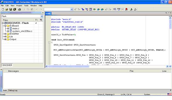
Replace that code with following code.and save it
#include "main.h"
#include "stm32f0xx_conf.h"
#define MS_DELAY_HSI (1000)
#define SECOND_DELAY (1000*MS_DELAY_HSI)
uint32_t TickValue=0;
void Init_GPIO(void)
{
GPIO_InitTypeDef GPIO_InitStructure;
RCC_AHBPeriphClockCmd (RCC_AHBPeriph_GPIOA | RCC_AHBPeriph_GPIOC | RCC_AHBPeriph_GPIOB, ENABLE);
GPIO_InitStructure.GPIO_Pin = GPIO_Pin_8 | GPIO_Pin_9 ;
GPIO_InitStructure.GPIO_Speed = GPIO_Speed_10MHz;
GPIO_InitStructure.GPIO_Mode = GPIO_Mode_OUT;
GPIO_InitStructure.GPIO_OType = GPIO_OType_PP;
GPIO_Init(GPIOC, &GPIO_InitStructure);
}
void TimingDelay_Decrement(void)
{
TickValue--;
}
void delay(uint32_t counts)
{
while(counts-- != 0) ;
}
void delay_ms(uint32_t n_ms)
{
SysTick_Config(8000*PLL_MUL_X - 30);
TickValue = n_ms;
while(TickValue == n_ms) ;
SysTick_Config(8000*PLL_MUL_X);
while(TickValue != 0) ;
}
int main(void)
{
Init_GPIO();
while(1)
{
GPIOC->ODR = 0x0300;
delay_ms(1000);
GPIOC->ODR = 0x0000;
delay_ms(1000);
}
}
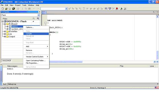
5 . In the Project menu, select to compile your project.
6. If your project is successfully compiled, the following window is displayed.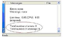
Debugging and running your project
In the IAR Embedded Workbench IDE, from the Project menu, select Download and Debug or, alternatively, click the Download and Debug button the in toolbar, to program the Flash memory and begin debugging.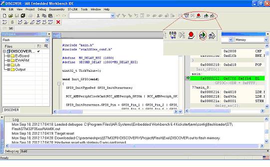
Then press the go button as shown in bellow fig.
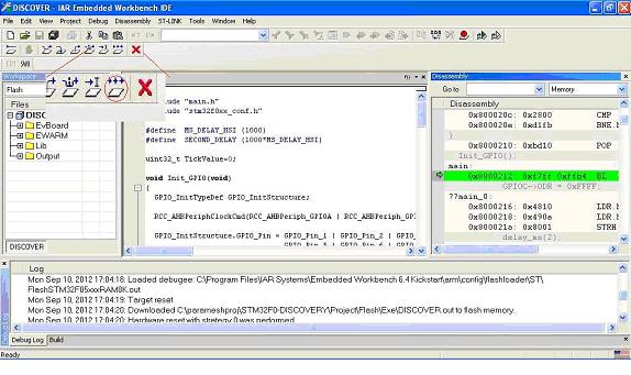
Then You can observe 'Green and Red LED blinking' in development board

Another sample program is explained in the next module.
Click below to visit next and other modules:
Module 4bsample: Sample program using STM32F0 Discovery
Module 5C: ARM Cortex M0 features and details -1
Module 6b: Sample program-2 (interfacing keypad)
Module 7: Serial communication concepts -1
Module 9: Controller Area Networking (CAN)
Module15: SRAM memory interface
Module16: Flash memory interface
Module17: LCD display panel interface
Module18: Touch pane interface
Module19: Audio/video interface
Previous Modules
Module 1: Introduction to Embedded Systems: Definition, application and future.
Module 2: Microprocessor, Microcontroller, MCU Manufacturers, introduction to programming.