Important Note: EE Herald has now (from October 2012) published embedded systems design practice using latest kits from ST Microelectronics and NXP Semiconductors based on the popular ARM Cortex M0 processor core. The old AME 51 kit explained from next paragraph in this module is not avaialable in the market now. We strongly recommend not to use AME 51 kit, instead read our module3b based on ARM Cortex M0 powered ST MIcro's Disocvery kit and and module3a based on ARM Cortex M0 powered NXP LPCXpresso kit to get into practical learning of embedded systems programming.
Installaion of OKI's AME 51 kit:
The items bundled with AME-51 Lite kit are,
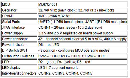
AME-51 Lite evaluation board with ML67Q4051 MCU on board
Serial RS232 cable - 9-pin male/female
OKI AME-51 Lite CD
Quick Start Guide
Kit does't provide 5V DC power suppy. It has to be purchased separately from any electronic shop. The rating of this power supply is,
Output Voltage = 5 to 7.5V unregulated DC Voltage
Current rating = 1Amp
with a 2.1 mm power adapter (Center pin positive)
The components on the AME-51 Lite evaluation board are,
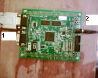
1. White cable above number '1' is RS 232 cable.
2. Black plug below number '2' is power plug.
Kit installation
Please follow these below steps to connect the board to your PC.

Place your board at a convenient place next to your PC.
Plug in 5V DC adapter to CPU board. Ensure your 5V DC power supply plug's center pin is positive and it should be of size 2.1 mm. Also make sure your 5V DC adapter current rating is 1Amp.
Connect the provided serial cable from your PC's serial port to the board serial port UART0
There is an 8 position DIP switch to tell the board what to do.
Board can go into four operating modes through four different configurations of the switch.
Here is the switch position table for the four modes.
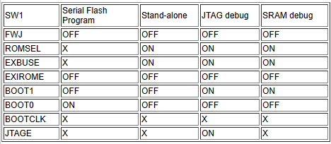
X - Dont care (can be either Off or On)
Default set position is stand-alone mode. If not in stand-alone mode, set it to stand-alone mode.
Installation of software part (compiler):
Load the CD provided in the kit into your PC's CD ROM drive and look for ame51setup.exe and double click to install. Follow the easy instructions and complete the installation. It's must to install it on C drive to avoid the complexity of changing root setting in the makefiles.
Unzip the file ttermp23 and extract them to a folder. In the unzipped files click setup.exe to install Tera Term Terminal Emulator software. Follow the simple instructions and complete the installation.
This software will only work on following Operating Systems
Windows XP professional
Windows 2000 with service pack 1 installed
Windows 98 second edition
At this stage both hardware and software installation is complete.
Important Note: EE Herald has now (from October 2012) published embedded systems design practice using latest kits from ST Microelectronics and NXP Semiconductors based on the popular ARM Cortex M0 processor core. The old AME 51 kit installation explained above in this module is not avaialable in the market now. We strongly recommend not to use AME 51 kit, instead read our module3b based on ARM Cortex M0 powered ST MIcro's Disocvery kit and and module3a based on ARM Cortex M0 powered NXP LPCXpresso kit to get into practical learning of embedded systems programming.

Click below to visit next module:
Module 4: Sample programs -1 for ARM7 TDMI MCU
Module 5: OKI ARM Processor Architecture.
Module 6: Sample programs -2 for ARM7 TDMI MCU
Module 3a: Installation of ARM Cortex M0 based LPCXpresso kit from NXP Semiconductor and sample code
Module 3b: Installation of ARM Cortex M0 based STM32F0 kit from ST Microelectronics and sample code
Module 7: Serial communication concepts -1
Module 9: Controller Area Networking (CAN)
Module15: SRAM memory interface
Module16: Flash memory interface
Module17: LCD display panel interface
Module18: Touch pane interface
Previous Modules
Module 1: Introduction to Embedded Systems: Definition, application and future.
Module 2: Microprocessor, Microcontroller, MCU Manufacturers, introduction to programming.
ABOUT THIS COURSE:
Totally EEHerald plan to bring 12 modules. You can be assured of completing basic course in Embedded Systems after studying and practicing exercises in all the modules. We will give priority to programming and serial communications (SPI, USB, CAN etc..) part. To receive a copy of total course syllabus, please email to us.
This free tutorials on embedded systems is prepared by embedded professionals with more than10 years of industrial experience, however we want your feedback on this course content; please email your questions, suggestions and comments to editor@eeherald.com. Your questions on present modules will be answered in the revised modules. We may change the course content based on the majority of your requests and feedbacks.
Please let your friends know about this course, we request you to email this link to your friends and colleagues who are interested in embedded system.